Table of Contents
Advertisement
Quick Links
Right choice for ultimate yield
LSIS strives to maximize customers' profit in gratitude of choosing us for your partner.
Programmable Logic Controller
High Speed Counter Module
XGB Series
Read this manual carefully before
installing, wiring, operating, servicing
or inspecting this equipment.
Keep this manual within easy reach
for quick reference.
User's Manual
XBF-HO02A
XBF-HD02A
http://eng.lsis.biz
Advertisement
Table of Contents

Related Manuals for LS Industrial Systems XBF-HO02A


Summary of Contents for LS Industrial Systems XBF-HO02A
- Page 1 LSIS strives to maximize customers' profit in gratitude of choosing us for your partner. Programmable Logic Controller High Speed Counter Module User’s Manual XGB Series XBF-HO02A XBF-HD02A Read this manual carefully before installing, wiring, operating, servicing or inspecting this equipment.
- Page 2 Safety Instruction Before using the product … For your safety and effective operation, please read the safety instructions thoroughly before using the product. ► Safety Instructions should always be observed in order to prevent accident or risk with the safe and proper use the product.
- Page 3 Safety Instruction Safety Instructions for design process Warning Please install a protection circuit on the exterior of PLC so that the whole system may operate safely regardless of failures from external power or PLC. Any abnormal output or operation from PLC may cause serious problems to safety in whole system. Install protection units on the exterior of PLC like an interlock circuit that deals with opposite operations such as emergency stop, protection circuit, and forward/reverse rotation or install an interlock circuit that deals with high/low limit under its position controls.
- Page 4 Safety Instruction Safety Instructions for design process Caution I/O signal or communication line shall be wired at least 100mm away from a high-voltage cable or power line. Fail to follow this instruction may cause malfunctions from noise Safety Instructions on installation process Caution ...
- Page 5 Safety Instruction Safety Instructions for wiring process Warning Prior to wiring works, make sure that every power is turned off. If not, electric shock or damage on the product may be caused. After wiring process is done, make sure that terminal covers are installed properly before ...
- Page 6 Safety Instruction Safety Instructions for test-operation and maintenance Warning Don’t touch the terminal when powered. Electric shock or abnormal operation may occur. Prior to cleaning or tightening the terminal screws, let all the external power off including PLC power. If not, electric shock or abnormal operation may occur. ...
- Page 7 Safety Instruction Safety Instructions for waste disposal Caution Product or battery waste shall be processed as industrial waste. The waste may discharge toxic materials or explode itself.
- Page 8 Revision History Revision History Version Date Remark Page V 1.0 2012.05 First Edition ※ The number of User’s manual is indicated right part of the back cover. Copyright (c) 2012 LSIS Systems Co., Ltd All Rights Reserved.
- Page 9 About User’s Manual Thank for purchasing PLC of LS Industrial System Co.,Ltd. Before use, make sure to carefully read and understand the User’s Manual about the functions, performances, installation and programming of the product you purchased in order for correct use and importantly, let the end user and maintenance administrator to be provided with the User’s Manual.
-
Page 10: Table Of Contents
◎ Table of Contents ◎ C h a p t e r 1 O v e r v i e w … … … … … … … … … … … … … … … … … … … … … … … … … … … 1 - 1 Chapter 2 Specifications …………………………………………………………... - Page 11 ............................4-4 ARAMETERS ETTING 4.2.1 Parameters setting screen ..........................4-4 ............................4-6 ONITORING AND 4.3.1 Monitoring/Test screen ............................ 4-6 ............................4-9 EGISTER EVICES 4.4.1 View variables ..............................4-9 4.4.2 Register U Devices ............................4-9 ..................... 4-12 EGISTRATION OF PECIAL MODULE VARIABLE 4.5.1 Global/Direct Variables screen ........................
- Page 12 7.2.15 Error status and error code ........................... 7-27 7.2.16 Hold count when power fails ......................... 7-28 Chapter 8 Troubleshooting ………………………………………………………… 8-1 ~ 8-9 ................................ 8-1 RROR CODE ............................... 8-2 ROUBLESHOOTING 8.2.1 LED display status of HS counter module ...................... 8-2 8.2.2 Counter status of HS counter module ......................
-
Page 13: Chapter 1. Overview
Chapter 1. Overview XGB High Speed counter modules are designed for XGB(XBM/XBC/XEC) series and used with XGT PLC CPU. And XBF-HO02A(Open Collector type) , XBF-HD02A(Line Drive type) modules are available. 1.1 Characteristic High Speed Counter modules can count the high speed pulses which can not be processed by CPU module’s counter instructions (CTU, CTD, CTUD etc.), up to binary value of 32 bits (-2,147,483,648 ~ 2,147,483,647). -
Page 14: Chapter 2 Specifications
Chapter 2 Specifications Chapter 2 Specifications 2.1 General Specifications General specifications of XGT series Item Specification Related specifications Operating 0℃∼+55℃ temperature Storage -25℃∼+70℃ temperature Operating 5∼95%RH, Non-condensing humidity Storage humidity 5∼95%RH, Non-condensing For discontinuous vibration Frequency Acceleration Amplitude Number 10≤f< 57㎐ 0.075mm 57≤f≤150㎐... -
Page 15: Performance Specifications
Chapter 2 Specifications 2.2 Performance Specifications Specifications of High Speed counter module’s basic performance, preset/gate input and transistor output are as described below. 2.2.1 Performance specifications Specification Item XBF-HO02A XGF-HD02A Signal A-phase, B-phase Count Input type Voltage input (Open Collector) -
Page 16: Pulse Input Specification
Chapter 2 Specifications 2.2.2 Pulse input specification Specification Item Open collector Line driver DC 24V DC 12V DC 5V Input volatage (17.0V~26.4V) (9.8V~13.2V) (4.5V~5.5V) Input current 7mA~11mA 7mA~11mA 7mA~11mA RS-422A line driver (5V level)/HTL line Min. On guaranteed 17.0V 9.8V 4.1V Driver(24V level) voltage... -
Page 17: Part Names
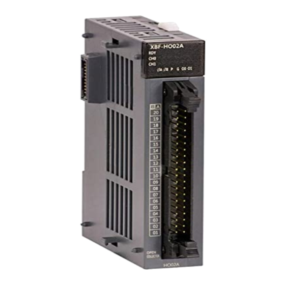
Chapter 2 Specifications 2.3 Part Names 2.3.1 Part Names Name Contents On: relevant channel pulse inputting, Preset/Auxiliary function signal inputting, Run LED Commparison outputting (ΦA, ΦB, P, G, O0, O1) Off: No input of relevant channel pulse, No input of preset/auxiliary function signal, No output ①... -
Page 18: Specification Of Interface With External Devices
Chapter 2 Specifications 2.3.2 Specification of interface with external devices 1. Arrangement of connector pins (1) XBF-HO02A Pin arrangement Signal name A24V A phase pulse input 24V A12V A phase pulse input 12V A phase pulse input 5V ACOM A phase pulse input COM... - Page 19 Chapter 2 Specifications 2. Internal circuit Describes internal circuit of HSC module to connect HSC module with external device (1) XBF-HO02A Pin No. Internal circuit Terminal Signal name ① A24V A phase pulse input 24V ① ② A12V A phase pulse input 12V ②...
- Page 20 Chapter 2 Specifications (2) XBF-HD02A Pin. No. Internal circuit Terminal Signal ① AⅠphase differentiation input + ② AII+ AⅡ phase differentiation input + ① ③ AⅠ phase differentiation input - ② ④ AII- AⅡ phase differentiation input - ③ ① BⅠ...
- Page 21 Connection cable Classification Model Name Name Length Content For extension module XBF-HO02A HSC module TG7-1H40S C40HH-□□PH-XBI 0.5 ~ 10m connection XBF-HO02A (40Pin) (b) In case of wiring HSC Module by using TG7-1H40S and C40HH-□□SB-XBI, relationship of HSC module signal name and I/O link board terminal number is as follows.
-
Page 22: Functions
Chapter 2 Specifications 2.4 Function 2.4.1 Input pulse type 1. 1 phase input (1) Up/Down operation by program setting (a) 1 phase 1 input 1 multiplication input When input pulse of A phase is rising, count operates and up/down count operation is set by program 1)High Active Mode Up/Down count classification A phase pulse rising... - Page 23 Chapter 2 Specifications (b) 1 phase 1 input 2 multiplication input When input pulse of A phase is rising and falling, count operates and up/down count operation is set by program Up/Down count classification A phase pulse rising A phase pulse falling Up/Down count setting Off Up count (+1) Up count (+1)
- Page 24 Chapter 2 Specifications (2) Up/Down count operation by B phase input signal (a) 1 phase 2 input 1 multiplication input When input pulse of A phase is rising, count operates and up/down count operation is set by level of B phase input pulse. 1) High Active Mode Up/Down count classification A phase pulse rising...
- Page 25 Chapter 2 Specifications (b) 1 phase 2 input 2 multiplication input When input pulse of A phase is rising and falling, count operates and up/down count operation is set by level of B phase input pulse. 1) High Active Mode Up/Down count classification A phase pulse rising A phase pulse falling...
- Page 26 Chapter 2 Specifications 2. 2 phase input (1) 2 phase 1 multiplication input 1) High Active Mode When input pulse of A phase is ahead of B phase input pulse, at rising edge of A phase input pulse, Up count is operated. When input pulse of B phase is ahead of A phase input pulse, at falling edge of A phase input pulse, Down count is operated.
- Page 27 Chapter 2 Specifications (2) 2 phase 2 multiplication input When input pulse of A phase is ahead of B phase input pulse, at rising and falling edge of A phase input pulse, Up count is operated. When input pulse of B phase is ahead of A phase input pulse, at rising and falling edge of A phase input pulse, Down count is operated.
- Page 28 Chapter 2 Specifications 3. CWCCW(ClockWise/Counter ClockWise) input Count is operated at rising edge of A phase inpulse or B phase input pulse and Up/Down count operation is determined by level of A or B input pulse 1) High Active Mode Up/Down count classification A phase pulse rising A phase pulse falling B phase pulse rising...
-
Page 29: Counter Mode
Chapter 2 Specifications 2.4.2 Count Mode Linear count (1) Linear Count range: -2,147,483,648 ~ 2,147,483,647 (2) Up count If count value reaches the maximum value while increased, Carry will occur, and Carry occurs, count stops and increasing is not available but decreasing is available. (3) Down count If count value reaches the minimum value while decreased, Borrow will occur and Borrow occurs, count stops and decreasing is not available but increasing is available... - Page 30 Chapter 2 Specifications 2) Down count If count value reaches minimum value during decreasing count, Borrow only occurs and count is executed starting from max. value Count Ring count max value Count start Input pulse : Not included : Included Ring count min value Borrow...
- Page 31 Chapter 2 Specifications 2) Down count If count reaches min. value, borrow occurs and count is changed into ring count max. value. Count is executed until 2,147,483,647. If count reaches -2,147,483,648, count is changed into 2,147,483,648 and executed again. Count 2,147,483,647 Count start Ring count max...
-
Page 32: Preset
Chapter 2 Specifications 2.4.3 Preset (1) When Enable Preset is On, current count is changed into preset setting value. Only with setting of preset, current count is not changed and you have to execute the Enable Preset ot change the current count. (2) Operation method (a) Internal preset Setting preset value ... -
Page 33: Compared Output
Chapter 2 Specifications 2.4.4 Compared output (1) High Speed counter module has a compared output function used to compare present count value with compared value in size to output as compared. (2) Available compared outputs are 2 for 1 channel, which can be used separately. (3) Compared output conditions are 7 associated with <, ≤, =, ≥, >, ≤... - Page 34 Chapter 2 Specifications 3. Count value = Compared value If present count value is equal to compared value, output is sent out, and even if count value increases to be greater or less than compared value, output is kept On. In order to turn the output Off, identical reset signal is to be On. Count 123456 123457...
- Page 35 Chapter 2 Specifications 5. Count value > Compared value If present count value is greater than compared value, output is sent out, and if count value decreases to be less than or equal to compared value, output is not sent out. Count 123456 123457...
- Page 36 Chapter 2 Specifications 7. Count value ≤ Compared value min., Count value ≥ Compared value max. If present count value is less than or equal to compared value 1 and greater than or equal to compared value 2, output is sent out, and if count value increases/decreases to exceed compared value’s range, output is not sent out.
-
Page 37: Carry Signal
Chapter 2 Specifications 2.4.5 Carry Signal Carry Signal occurs (1) When count range maximum value of 2,147,483,647 is reached during Linear Count. (2) When maximum value of Ring Count changed to the minimum value during Ring Count. Count when Carry Signal occurs (1) Count stops if Carry occurs during Linear Count. -
Page 38: Auxiliary Mode
Chapter 2 Specifications 2.4.7 Auxiliary mode High Speed counter module provides 6 auxiliary modes as well as basic count function and compared output function. In order to use the auxiliary modes, auxiliary mode enable signal is to be “On”. Notes (1) To use auxiliary function by program, turn off the external auxiliary mode and turn on Enable Auxiliary (2) To use auxiliary function by an external signal, turn on the external auxiliary mode and turn on External auxiliary input signal (GATE). - Page 39 Chapter 2 Specifications 2. Count Latch (1) When auxiliary mode enable signal is On, present count value is latched (2) Setting method Set auxiliary mode setting mode to 2 Auxiliary mode enable signal On Current count Count start -200 Latch count -200 Auxiliary...
- Page 40 Chapter 2 Specifications 3. Sampling Count (1) When auxiliary mode enable signal is On, it counts for a specified time. (2) Setting method Set auxiliary mode setting mode to 3 Time setting Auxiliary mode enable signal On (3) Display during auxiliary mode operation Sampling Count function operates for a specified time when auxiliary mode enable signal is On, and the auxiliary mode in progress signal is On at the same time.
- Page 41 Chapter 2 Specifications 4. Input Frequency Measure (1) While auxiliary mode enable signal is On, it indicates frequency of input pulse. Unit of input frequency conforms to setting of frequency unit. (2) Setting method Set auxiliary mode setting mode to 4 Set frequency unit Auxiliary mode enable signal On. (3) Frequency input mode can be specified as below, whose update cycle and resolution will be decided based on the applicable mode.
- Page 42 Chapter 2 Specifications 5. Revolution/Unit time (1) While auxiliary mode enable signal is On, it calculates the number of input pulses for a specified time and indicates the revolution/unit time. To use this function, setting time and No. of pulse/revolution should be set. (2) Setting method Set auxiliary mode setting mode to 5 setting ...
- Page 43 Chapter 2 Specifications 6. Count Disable (1) While auxiliary mode enable signal is On, count operation stops. (2) Setting method Set auxiliary mode setting mode to 6 Auxiliary mode enable signal On (3) Display during auxiliary mode operation While auxiliary mode enable signal is On, Now Running signal is on Current count Count start -200...
-
Page 44: Chapter 3 Installation And Wiring
Chapter 3 Installation and Wiring Chapter 3 Installation and Wiring 3.1 Installation 3.1.1 Installation environment This product is of high reliance regardless of installation environment. However, for the sake of reliance and stability of the system, please pay attention to those precautions described below. (1) Environmental conditions (a) To be installed on the control panel waterproof and dustproof. -
Page 45: Wiring Precautions
Chapter 3 Installation and Wiring 3.2 Wiring Precautions 3.2.1 Wiring Precautions (1) Pay attention to do action about external noise during wiring for the pulse input of the high counter module. (2) Surely use twisted pair shielded cable, grounded with 3 class applied. (3) Keep away from power cable or I/O line which may cause noise. -
Page 46: Example Of Dc5V Voltage Output Wiring
- If the pulse generator is voltage output type, example of wiring with HSC is as shown below; - The wiring will be the same if the pulse generator (Encoder or Manual pulse generator) of voltage output type is used through Totem Pole output. XBF-HO02A Pulse Generator A24V... -
Page 47: Example Of Dc12V Npn Open Collector Output Wiring
3.2.3 Example of DC12V NPN Open Collector output wiring This is the wiring example which it used the pulse generator (Encoder or Manual pulse generator) of NPN Open Collector output type. Pulse Generator XBF-HO02A A24V A24V Twist Shield Cable A12V... - Page 48 In case external line noise environment, Between pulse generator(encoder or manual pulse generator) and HSC wiring need to attach a resistance by noise to protect malfunction as below the wiring example. (External Pull Up Resistance use to adjust specification of external device.) Pulse generator XBF-HO02A A24V A24V Twist Shield Cable...
-
Page 49: Example Of Dc24V Pnp Open Collector Output Wiring
3.2.4 Example of DC24V PNP Open Collector output wiring This is the wiring example which it used the pulse generator (Encoder or Manual pulse generator) of PNP Open Collector output type. Pulse Generator XBF-HO02A A24V A12V Phase A Twist Shield Cable... -
Page 50: Example Of Line Driver Output Wiring
Chapter 3 Installation and Wiring 3.2.5 Example of Line Driver output wiring This is the wiring example which it used the pulse generator (Encoder or Manual pulse generator) of RS-422A Line Driver (5V level) output type. XBF-HD02A Pulse Generator Twist Shield Cable OUTA+ OUTA- Twist Shield Cable... -
Page 51: Chapter 4 Operation Procedures And Monitoring (Xg5000)
Chapter 4 Operation Procedures and Monitoring Chapter 4 Operation Procedures and Monitoring Operation setting and monitor functions of XG5000 program will be described in this chapter among operation methods of High-speed counter module. 4.1 XG5000 Excution 4.1.1 Execution and Connection of XG5000 After XG5000 installed, click XG5000 execution icon to display the initial screen of XG5000 program as shown below. - Page 52 Chapter 4 Operation Procedures and Monitoring 3) Project screen is as below. Project screen of XBM series Project screen of XBC series...
- Page 53 Chapter 4 Operation Procedures and Monitoring Project screen of XEC series 4) If a project is created, click [Online]-[Connection Settings] or on the icon menu to specify the connection method and connection stage, and then click [Settings] to specify the communication port and the communication speed(115,200).
-
Page 54: Parameters Setting
Chapter 4 Operation Procedures and Monitoring 4.2 Parameters Setting This description is based on XG5000 Project of XBC series, because it is the same to parameter setting method of XBM/XBC/XEC series. 4.1.2 Parameters setting 1) Double-click [I/O parameters] on the [Project Window] to the left of the project created on XG5000. 2) If [I/O parameters setting] window is displayed, click the module area of the applicable slot to select the applicable module... - Page 55 Chapter 4 Operation Procedures and Monitoring ) Double-click the applicable slot selected to specify the parameters, or click [Details] to display the screen where parameters can be set. 4) Set parameters as necessary for operation on the parameters setting window. ※...
-
Page 56: Monitoring And Test
Chapter 4 Operation Procedures and Monitoring 4.3 Monitoring and Test This description is based on XG5000 Project of XBC series, because it is the same to parameter setting method of XBM/XBC/XEC series. 4.3.1 Monitoring and Test After connected to PLC CPU through XG5000, click [Online]-[Special Module Monitoring] or on the icon menu to display the screen as shown below. - Page 57 Chapter 4 Operation Procedures and Monitoring Select the applicable module and click the monitoring button to display the monitoring/ test screen as shown below, whose functions are as follows; • On the upper monitoring screen, each special module’s monitoring item values are displayed. •...
- Page 58 Chapter 4 Operation Procedures and Monitoring In order to monitor the I/O contact status, click the applicable channel’s flag monitoring button to display the monitoring screen where each I/O contact status can be checked.
- Page 59 Chapter 4 Operation Procedures and Monitoring 4.4 Registration of U Devices It is described to the method to register automatically U devices in XG5000 Project of XBC series. 4.4.1 Variable/Comment screen If you double click [Variables/Comment] of [Project Window], variables and comments which was registered already are displayed.
- Page 60 Chapter 4 Operation Procedures and Monitoring 4.4.2 Registration of U Devices Select [Edit] [Register U Device]. ( First, [Variable/Comment] window has to be executed. ) Click [Yes] to complete the U device registration that is set at [I/O parameter setting] 4-10...
- Page 61 Chapter 4 Operation Procedures and Monitoring 4-11...
-
Page 62: Registration Of Special Module Variable
Chapter 4 Operation Procedures and Monitoring 4.5 Registration of Special module variable It is described to the method to register automatically variables[Global variables/Constants] of high speed counter module in XG5000 Project of XEC series. 4.5.1 Global/Direct Variables screen If you double click [Global/direct Variables] of [Project Window], variables and comments which was registered already are displayed. - Page 63 Chapter 4 Operation Procedures and Monitoring Click [Yes] to complete the special module variables registration that is set at [I/O parameter setting] 4-13...
-
Page 64: Chapter 5 Internal Memory & I/O Signals
Chapter 5 Internal Memory & I/O Signals Chapter 5 Internal Memory & I/O Signals 5.1 Internal Memory High Speed Counter has the internal memory used for data “Write/Read” to/from PLC CPU. The commands used for “Write” from PLC CPU to High Speed Counter‟s internal memory are PUT and PUTP, and the commands used for “Read” are GET and GETP. Configuration of the internal memory and the data is as described below. -
Page 65: Details & Data Configuration
Chapter 5 Internal Memory & I/O Signals 5.1.2 Details & Data Configuration (1) Count mode setting (CH0: 0 address, CH1: 25 address) Setting value Details Linear count Ring count (2) Pulse input mode setting (CH0: 1 address, CH1: 26 address) Setting value Details 2-phase 1-multiplication... -
Page 66: I/O Signals
Chapter 5 Internal Memory & I/O Signals 5.2 I/O Signals (1) Output setting area Channel 0 Channel 1 Details Uxy.02 ~ Uxy.03 Uxy.12 ~ Uxy.13 Present count value Uxy.04 ~ Uxy.05 Uxy.14 ~ Uxy.15 Latch count value Uxy.06 ~ Uxy.07 Uxy.16 ~ Uxy.17 Sampling count value Uxy.08 ~ Uxy.09... -
Page 67: Global Constant
Chapter 6 Global Constant and Global Variable Chapter 6 Global Constant and Global Variable It is described to global constant and global variable for XEC series. Remark It is terminology for XGB IEC type PLC series to Global constant(VAL_GLOBAL_CONST) and Global variable(VAL_GLOBAL). In XBM/XBC series, global constant is equivalent to the internal memory, global variable is to input/output signal(U device). -
Page 68: The Configuration And Contents Of Data
Chapter 6 Global Constant and Global Variable Remark (1) „Fxy‟ : „x‟ means the base number of the high speed counter module, „y‟ means the slot number of it. (2) Constant value can not be modified, because it is the address of input data area. (3) Constant value is the same as the internal memory address of XBM/XBC series. - Page 69 Chapter 6 Global Constant and Global Variable 5. The frequency display unit of input frequency measure (channel 0: , channel 1: _Fxy_CH0_FREQ_MODE _Fxy_CH1_FREQ_MODE Setting value Contents 10Hz 100Hz 1000Hz(=1kHz) 6. Setting area of comparison output status Constant Contents Default value Low Active Low Active High Active...
- Page 70 Chapter 6 Global Constant and Global Variable 6.2 Global Variable 1. The range of output data Channel 0 Channel 1 Contents _xy_CH0_CNT _xy_CH1_CNT Current count value _xy_CH0_FRQ _xy_CH1_FRQ Count latch _xy_CH0_LTH _xy_CH1_LTH Sampling count _xy_CH0_RNG _xy_CH1_RNG Input frequency count _xy_CH0_RPU _xy_CH1_RPU Revolution per unit time Remark...
- Page 71 Chapter 7 Programming Chapter 7 Programming Here describes how to program by using instruction (XBM/XBC series) or function block (XEC) at scan program of XG5000 7.1 Instruction and Function Block Here describes instruction and function block to read and write data of HSC module at XGB CPU module. Remark There is difference on terminology used in XBM/XBC series and XEC series.
- Page 72 Chapter 7 Program (a) How to set base and slot number 1) Basic base Slot 0 Slot 1 Slot 2 Slot 3 Slot 4 (3) Use of GET/GETP instruction (a) HSC module is installed at slot 8 of basic base and While M00000 is On, it transmits the data (data1, data2) of internal memory 5 and 6 to D00015 and D00016.
- Page 73 Chapter 7 Programming 2. PUT/PUTP instruction Instruction to write data from XGB CPU module to internal memory area (1) PUT/PUTP instruction Level Always executed with execution condition On PUTP Edge Executed with execution condition of operation Start (2) Configuration of PUT/PUTP instruction Execution condition Type...
- Page 74 Chapter 7 Program 7.1.2 Function Block of XEC 1. GET function block Function Block to read data of Global constant area at XEC CPU module. That data can be saved at variable area of XEC CPU module (Except flag area). (1) GET function block configuration Function block Classification...
- Page 75 Chapter 7 Programming (b) It transmits data at the rising edge of execution condition Read1 GET_WORD 읽기1 DONE BASE STAT 출력데이터1 SLOT DATA OutputData1 _F01_CH0 MADDR _CNT_MODE 2. PUT function block Function Block to write the data into Global constant area at XEC CPU module. (1) Configuration of PUT function block Function Block classification...
- Page 76 Chapter 7 Program PUT_WORD PUT_WORD Write1 Write1 DONE DONE BASE STAT BASE STAT SLOT SLOT _F0A_CH0 MADDR MADDR _CNT_MODE DATA DATA InputData1 InputData1 Remark (1) Operations of above two examples are same. (2) For detail of Global variable, refer to ‘XG5000 user manual’. (b) It transmits data at the rising edge of execution condition PUT_WORD Write1...
- Page 77 Chapter 7 Programming 7.2 Program 1. XGB system is explained referring to the following system HSC module is equipped at slot 1 of basic base. 7.2.1 Count mode setting Example explaing how to set Ring Count Min. and Max. As for setting method by ‘I/O Parameter’, refer to Chapter 4. 1.
- Page 78 Chapter 7 Program (2) Scan program of XECseries.
- Page 79 Chapter 7 Programming Remark (1) Since instruction PUT (Function Block PUT_DWORD) is used at scan program example of XBM/XBC (XEC) series, while input contact point is On, data is transmitted into HSC module. So, if data is changed, it is transmitted into HSC module automatically.
- Page 80 Chapter 7 Program 7.2.2 Pulse input mode setting Program example setting pulse input mode 1. Setting contents Parameter Pulse input mode 3: CW/CCW 3: CW/CCW 2. Program (1) Scan program of XBM/XBC series (2) Scan program of XECseries 7-10...
- Page 81 Chapter 7 Programming 7.2.3 Counter check Program example checking current counter and operation by auxiliary function. 1. Program (1) Scan program of XBM/XBC series (2) Scan program of XECseries Remark or ‘Change Columns’ of ‘View’ In Scan program of XGI/XGR, the number of cell is changed by using icon 7-11...
- Page 82 Chapter 7 Program 7.2.4 Preset value setting and enable preset Program example about how to set preset value and enable preset 1. Setting content Parameter Preset value 1000 1000 2. Program (1) Scan program of XBM/XBC series (2) Scan program of XEC 7-12...
- Page 83 Chapter 7 Programming 7.2.5 Enable counter Program example executing Enable counter 1. Program (1) Scan program of XBM/XBC series (2) Scan program of XECseries 7.2.6 Carry/borrow detection reset Program example resetting the detected carry/borrow signal 1. Program (1) Scan program of XBM/XBC series (2) Scan program of XECseries 7-13...
- Page 84 Chapter 7 Program 7.2.7 Auxiliary mode setting and Enable auxiliary function Program example setting auxiliary mode and executing Enable auxiliary function. You can check the operation result of auxiliary function at 7.2.3 Counter check. 1. Counter Clear When auxiliary function is on, change current counter as 0. (1) Setting contents Parameter Auxiliary mode...
- Page 85 Chapter 7 Programming 2. Counter latch When Enable auxiliary is on, it indicates current counter at counter latch. (1) Setting contents Parameter Auxiliary mode 2: Counter latch 2: Counter latch (2) Program (a) Scan program of XBM/XBC series (b) Scan program of XECseries 7-15...
- Page 86 Chapter 7 Program 3. Sampling Count Counter from when Enable auxiliary is on to setting time is indicated at sampling counter. (1) Setting content Parameter Auxiliary mode 3: Sampling Count 3: Sampling Count Range value 5000 5000 (2) Program (a) Scan program of XBM/XBC series (b) Scan program of XECseries 7-16...
- Page 87 Chapter 7 Programming 4. Input Freq. Measure While Enable auxiliary function is on, input pule is indicated at input frequency. Unit of input frequency is depending on setting of Frequency Mode. (1) Setting content Parameter Auxiliary mode 4: Input Freq. measure 4: Input Freq.
- Page 88 Chapter 7 Program 5. Revolution/Unit time While Enable auxiliary mode is on, input pulse is calculated and indicated at revolution/unit time. For revolution/unit time, Range value and Pulse/Rev value should be set. (1) Setting contents Parameter Auxiliary mode 5: Revolution/Unit time 5: Revolution/Unit time Range value 1000...
- Page 89 Chapter 7 Programming 6. Counter Disable While Enable auxiliary is on, counting is not executed. (1) Setting contents Parameter Auxiliary mode 6: Count Disable 6: Count Disable (2) Program (a) Scan program of XBM/XBC series (b) Scan program of XECseries 7-19...
- Page 90 Chapter 7 Program 7.2.8 Up/down count selection Program example selecting UP/Down count when input pulse is set as 1 phase 1 input 1 mutiplication/2 multiplication 1. Program (a) Scan program of XBM/XBC series (b) Scan program of XECseries 7.2.9 Use of external preset signal Program examples allowing Enable preset by external preset signal and executing reset when external preset signal is detected 1.
- Page 91 Chapter 7 Programming 7.2.10 Use of external auxiliary function signal Program example allowing Enable auxiliary function by external auxiliary function signal 1. Program (a) Scan program of XBM/XBC series (b) Scan program of XECseries 7-21...
- Page 92 Chapter 7 Program 7.2.11 Type of comparison and comparison value setting Program example explain type of comparison and comparison value setting 1. Setting content Parameter Comp output 0 Comp output 1 Comp output 0 Comp output 1 1: ≤ 5: ≤ ≤ 1: ≤...
- Page 93 Chapter 7 Programming (b) Scan program of XECseries 7-23...
- Page 94 Chapter 7 Program 7.2.12 Enable comparison, Enable comparison output, Comparison agreement reset Program example executing Enable comparison, Enable comparison output, Comparison agreement reset 1. Program (a) Scan program of XBM/XBC series (b) Scan program of XECseries 7-24...
- Page 95 Chapter 7 Programming 7.2.13 Comparison output status setting Program example setting status of comparison output when XGB (XBM/XBC/XEC) CPU module is STOP. 1. Setting content Parameter CH0, CH1 Comparison output status when XGB CPU module is STOP 1: Hold comparison output 2.
- Page 96 Chapter 7 Program 7.2.14 Input pulse Active level setting Program example input pulse active level setting of HSC module. 1. Setting content Parameter Active Level CH0 Input pulse active level High Active CH1 Input pulse active level Low Active 1. Program (a) Scan program of XBM/XBC series (b) Scan program of XEC series 7-26...
- Page 97 Chapter 7 Programming 7.2.15 Error status and error code Program example checking error status and error code occurred at HSC module 1. Program (a) Scan program of XBM/XBC series (b) Scan program of XEC series 7-27...
- Page 98 Chapter 7 Program 7.2.16 Hold count when power fails Program example holding current count To prepare when PLC power is off, current count is saved every scan and if PLC power restart, preset operation is executed with the saved count. 1.
- Page 99 Chapter 7 Programming (b) Scan program of XEC series 7-29...
- Page 100 Chapter 7 Program Remark (1) In the program, timer (TON) is used for safe operation of Preset value setting and preset allowance (2) In scan program of XEC series, to hold data of ‘CH0 current count’ and ‘CH1 current count’ when PLC power is off, the following setting is necessary.
- Page 101 Chapter 8 Troubleshooting Chapter 8 Troubleshooting How to shoot the troubles on the high speed counter module will be described. Description 8.1 Error code Description RDY LED Module error (ASIC Reset error) Blinks every Module error (ASIC Memory error) 0.2 sec. Module error (ASIC Register error) Counter type range exceeded Pulse input type range exceeded...
- Page 102 Chapter 8 Troubleshooting 8.2 Troubleshooting 8.2.1 LED display status of the high speed counter module RDY LED is Off. Go to 8.3.1 RDY LED blinks. Go to 8.3.2 8.2.2 Counter status of the high speed counter module The counter value is the same as before. Go to 8.3.3 Go to 8.3.4 The change of counter value is not consistent with operation status...
- Page 103 Chapter 8 Troubleshooting 8.3 Troubleshooting sequence 8.3.1 RDY LED Off RDY LED is Off. Is RDY LED Voltage of power module normal? Check and replace power module Other slot’s module normal? H/W defect Other slot’s module H/W defect H/W defect...
- Page 104 Chapter 8 Troubleshooting 8.3.2 RDY LED Blinks RDY LED blinks RDY LED blinks every 0.2 sec? RDY LED blinks every 1 sec? H/W defect After module Off →On, RDY LED blinks every 0.2 Operation parameters setting error. sec? Chang the setting data within the setting range H/W defect Check module’s base connection status...
- Page 105 Chapter 8 Troubleshooting 8.3.3 Counter operation error Counter operation error Power module’s Check and remove voltage normal? power module A-phase LED blinks? A, B LED On when External wiring voltage directly input on normal? counter input terminal? H/W defect Check and correct defect external wiring Counter operation...
- Page 106 Chapter 8 Troubleshooting 8.3.4 Counter value error Counter value error Let counter input as specified in As specified in input standard requirements. standard? Use twisted shielded cable for Input cable of twisted shielded? counter input wiring. Actions prepared Remove cause of the noise against noise? Kept away enough Keep counter input away from power...
- Page 107 Chapter 8 Troubleshooting 8.3.5 Output operation error Output operation error External power’s Check and correct external power voltage normal? Let it connected as specified in output specified in output standard? requirements. Output wiring Correct external wiring. normal? Output Value set per LED operates scan? correctly?
- Page 108 Chapter 8 Troubleshooting 8.4 Module status check through XG5000 system monitoring Module type, module information, OS version and module status of HSC module can be checked through XG5000 system monitoring function. 8.4.1 Execution sequence [Monitor] -> [System Monitoring] -> and on the module screen, click the right mouse button to display [Module Information]. 8.4.2 Module information 1.
- Page 109 Appendix 1 Terminology Appendix 1 Terminology 1. Pulse Used to turn voltage (current) On/Off for a short time, and pulse line is of continuous pulses Encoder Used mainly in subo-detector in order to detect speed and position, whose basic principle is that if infrared ray from LED passes the slit disk and reaches the light receiving element, analog electric sign is output which will be converted by voltage comparator to digital sign to be output.
- Page 110 Appendix 1 Terminology Compared Value Basic value used to compare counters in size. Carry Signal displayed when Linear count changes from 2,147,483,646 to 2,147,483,647 and when Ring count changes from the maximum value to the minimum value with increasing counter operation. Borrow Signal displayed when Linear count changes from -2,147,483,647 →...
- Page 111 Appendix 2 Dimensions Appendix 2 Dimensions Appendix 2 Dimensions Unit: ㎜ Remark XBF-HO02A and XBF-HD02A are same size. App2-1...
- Page 112 3. Since the above warranty is limited to PLC unit only, make sure to use the product considering the safety for system configuration or applications. Environmental Policy LS Industrial Systems Co., Ltd supports and observes the environmental policy as below. Environmental Management About Disposal LS Industrial Systems’...
- Page 113 Road Jebel Aali Free Zone Dubai, United Arab Emirates Tel : +31 (0)20 654 1420/Fax : +31 (0)20 654 1429 e-mail : junshickp@lsis.biz ■ Wuxi LS Industrial Systems Co., Ltd _ Wuxi, China Tel : 971-4-886-5360/Fax : 971-4-886-5361 e-mail : jungyongl@lsis.biz ■...
Need help?
Do you have a question about the XBF-HO02A and is the answer not in the manual?
Questions and answers