
Related Manuals for LS Industrial Systems GLOFA GM7U Series


Summary of Contents for LS Industrial Systems GLOFA GM7U Series
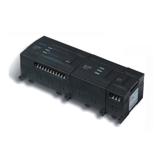
- Page 1 GLOFA GM7U Programmable Logic Controller Read this manual carefully before installing, wiring, operating, servicing or inspecting this equipment. Keep this manual within easy reach for quick reference.
- Page 2 SAFETY INSTRUCTIONS To prevent injury and property damage, follow these instructions. Incorrect operation caused by ignoring instructions may cause harm or damage. The consequences are indicated by the following symbols. This symbol indicates instant death or DANGER serious injury. This symbol indicates the possibility of death WARNING or serious injury.
- Page 3 SAFETY INSTRUCTIONS Design Precautions Warning Install a safety circuit external to the PLC that keeps the entire system safe even when there are problems with the external power supply or the PLC module. Otherwise, serious problems such as erroneous outputs or operations may occur. - Outside the PLC, construct mechanical damage preventing interlock circuits.
- Page 4 SAFETY INSTRUCTIONS Design Precautions Caution Do not bunch the control wires or communication cables with the main circuit, power wires, or close together. They should be installed 100mm (3.94 inches) or more from each other. Not doing so could result in noise that may cause erroneous operation. Installation Precautions Caution Use the PLC in an environment that meets the general specification...
- Page 5 SAFETY INSTRUCTIONS Wiring Precautions Warning Completely turn off the external power supply when installing or wiring. Not turning off the external power supply may cause an electric shock or damage to the product. Make sure that all terminal covers are correctly attached. Not attaching the terminal cover could result in an electric shock.
- Page 6 SAFETY INSTRUCTIONS Startup and Maintenance Precautions Warning Do not touch the terminals while power is on. This may cause an electric shock or erroneous operation. Switch all phases of the external power supply off when cleaning the module or retightening the terminal or module mounting screws. Not doing so could result in electric shock or erroneous operation.
-
Page 7: Table Of Contents
◎ Contents ◎ Chapter 1. General 1.1 Guide to Use This Manual ················· 1 - 1 1.2 Feature ························ 1 - 2 1.3 Terminology ······················ 1 - 4 Chapter 2. System Configuration 2.1 Overall Configuration ··················· 2 - 1 2.1.1 Basic System································································································ 2 - 1 2.1.2 Cnet I/F System·····························································································... - Page 8 4.4 Communication I/F Module ················· 4 - 21 4.4.1 Cnet I/F Module····························································································4 - 21 4.4.2 Fnet I/F Module ····························································································4 - 21 4.4.3 Pnet I/F Module ····························································································4 - 22 4.4.4 DeviceNet I/F Module ····················································································4 - 22 4.4.5 Rnet I/F Module····························································································4 - 22 Chapter 5.
- Page 9 5.7 Memory Configuration ··················· 5 - 33 5.8 I/O Allocation Method ··················· 5 - 35 5.9 Built-in Cnet Communication Setting Switch ········································ 5 - 35 5.9.1 Structure·····································································································5 - 35 5.9.2 Usage ········································································································5 - 36 5.10 External Memory Module ················· 5 - 37 5.10.1 Structure ···································································································5 - 37 5.10.2 Usage·······································································································5 - 37 5.11 RTC Option Module ···················...
- Page 10 Chapter 7. Usage of Various Functions 7.1 Built-in Functions ···················· 7 - 1 7.1.1 High Speed Counter Function··········································································· 7 - 1 7.1.2 Pulse Catch·································································································7 - 16 7.1.3 Input Filter···································································································7 - 17 7.1.4 PID Control ·································································································7 - 19 7.2 Special Modules ····················· 7 - 42 7.2.1 A/D·D/A Combination Module········································································7 - 43 7.2.2 A/D Conversion Module··················································································7 - 54...
- Page 11 8.2 User Defined Protocol Communication ············· 8 - 41 8.2.1 Introduction ·································································································8 - 41 8.2.2 Parameter Setting ·························································································8 - 41 8.2.3 Function Block ····························································································8 - 49 8.2.4 Example ·····································································································8 - 50 8.3 Modbus Protocol Communication ··············· 8 - 62 8.3.1 Introduction ·································································································8 - 62 8.3.2 Basic Specifications ······················································································8 - 62 8.3.3 Parameter Setting ·························································································8 - 66 8.3.4 Function Block ····························································································...
- Page 12 Chapter 10. Maintenance 10.1 Maintenance and Inspection ················ 10 - 1 10.2 Daily Inspection ···················· 10 - 1 10.3 Periodic Inspection ··················· 10 - 2 Chapter 11. Troubleshooting 11.1 Basic Procedure of Troubleshooting ············· 11 - 1 11.2 Troubleshooting ············································································ 11 - 1 11.2.1 Flowchart for when the “POWER”...
-
Page 13: Guide To Use This Manual
Chapter 1. General Chapter 1. General 1.1 Guide to Use This Manual This manual includes specifications, functions and handling instructions for the GLOFA-GM 7U series PLC. This manual is separated into the following chapters: Title Contents Describes the contents of this manual, the features of the PLC and Chapter 1 General terminologies... -
Page 14: Feature
Chapter 1. General 1.2 Feature 1) GLOFA-GM7U series have the following features. 1) GLOFA-GM series features (1) Designed on the basis of international standard specifications (IEC61131-3) Supports easy programming Provides IEC61131-3 Language (IL / LD / SFC) (2) Supports an open network by the international standard communication protocol (3) High speed processing with an embedded operation-dedicated processor. - Page 15 Chapter 1. General (9) Battery-less - With the EEPROM, the user program and parameter can be saved permanently without the battery. (10) Debugging function On-line debugging is available if the PLC Operation mode is set to debug mode. Executed by one command Executed by break-point settings Executed by the condition of the device Executed by the specified scan time...
-
Page 16: Terminology
Chapter 1. General 1.3 Terminology The following table gives a definition of terms used in this manual. Terms Definition Remarks Example) A standard element that has a specified function which CPU module, Module configures the system. The devices such as I/O board, which Power supply inserted onto the mother board or base unit. - Page 17 Chapter 1. General Terms Definition Remarks Variables used after the user’s definition of their names and Symbolic types. Declarations as ‘INPUT_0’ = %IX0.0.2, ‘RESULT Variable = %MD1234’ makes INPUT_0 and RESULT be able to used instead of %IX0.0.2 and %MD123 in programming. A peripheral device for the GLOFA-GM series.
- Page 18 Chapter 1. General Terms Definition Remarks Current flows from the output terminal to the load and the PLC output turn on. Source Output Fnet Fieldbus Network Cnet Computer Network Dnet DeviceNet Network 1 - 6...
-
Page 19: Chapter 2. System Configuration
Chapter 2. System Configuration Chapter 2. System Configuration The GLOFA-GM7U series has suitable to configuration of the basic, computer link and network systems. This chapter describes the configuration and features of each system. 2.1 Overall Configuration 2.1.1 Basic system Main unit Expansion module Expansion cable Total I/O points... -
Page 20: Cnet I/F System
Chapter 2. System Configuration 2.1.2 Cnet I/F system The Cnet I/F System are used for communication between the main unit and external devices using RS-232C/RS-422 Interface. The GM7U has a built-in RS-232C port, RS-485 port and has also G7L-CUEB for RS-232C, G7L-CUEC for RS-422. - Page 21 Chapter 2. System Configuration (3) 1:1 communication between HMI andGM7U via RS-485 built-in port RS-485 GM7U Series 2) 1:N communication system This method can connect a computer to multiple main units up to a maximum of 32 stations. (1) Via RS-422 Cnet I/F module Max.
-
Page 22: Product List
Chapter 2. System Configuration Product List The following describes functional model of the GLOFA-GM7Useries. 2.2.1 Product functional block Product configuration block for the GM7U series is as follows. Main Unit Expansion Modules Power supply Input signal Input signal Power Input Input supply DC24V... -
Page 23: Gm7U Series System Equipment Product
Chapter 2. System Configuration 2.2.2 GM7U series system equipment product 1) Main Unit Models I/O Point & Power Supply Built-in Function Remark Items 1) DC24V input 12 points - High speed counter G7M-DR20U 2) Relay output 8 points 1 phase: 100kHz 2Ch, 20 kHz 2Ch 3) AC 85 ~ 264[V] 2 phase: 50kHz 1Ch, 10 kHz 1Ch G7M-DR20U/DC... - Page 24 Chapter 2. System Configuration 2) Expansion/Special modules Items Models Specifications Remark • DC 24V input 6 points / Relay output 4 points G7E-DR10A G7E-DR20A • DC 24V input 12 points / Relay output 8 points G7E-RY16A • Relay output 16 points •...
-
Page 25: Chapter 3. General Specifications
Chapter 3. General Specifications Chapter 3. General Specifications 3.1 General Specifications The following shows the general specifications of the GLOFA-GM series. Item Specifications References Operating ambient 0 ~ 55 °C temperature Storage ambient −25 ~ +70 °C temperature Operating ambient 5 ~ 95%RH, non-condensing humidity Storage ambient... -
Page 26: Chapter 4. Names Of Parts
Chapter 4. Names of Parts Chapter 4. Names of Parts 4.1 Main Units ④ ⑤ ⑧ BUILT_IN CNET ⑦ PAU/REM STOP ROM MODE ② ① ⑥ ③ ③ ⑨ RS-485 Name Descriptions Indicates the status of the power supply to the system PWR LED On: when the supplied power is normal Off: when the supplied power is abnormal... - Page 27 Chapter 4. Names of Parts Name Descriptions Indicates the operating status of I/O ② I/O LED ③ Built-in RS-485 connector A connector for built-in RS-485 communications Designates the main unit’s operation mode RUN: runs the operation STOP: stops the operation ④...
- Page 28 Chapter 4. Names of Parts 2) G7M-DRT60U(N) 3) G7M-DT60U(N) 4) G7M-DT60U(P) 4 -3...
- Page 29 Chapter 4. Names of Parts 5) G7M-DR60U/DC 6) G7M-DRT60U(N)/DC 7) G7M-DT60U(N)/DC 4 -4...
- Page 30 Chapter 4. Names of Parts 8) G7M-DT60U(P)/DC 4.1.2 40-point main unit 1) G7M-DR40U 2) G7M-DRT40U(N) 4 -5...
- Page 31 Chapter 4. Names of Parts 3) G7M-DT40U(N) 4) G7M-DT40U(P) 5) G7M-DR40U/DC 4 -6...
- Page 32 Chapter 4. Names of Parts 6) G7M-DRT40U(N)/DC 7) G7M-DT40U(N)/DC 8) G7M-DT40U(P)/DC 4 -7...
- Page 33 Chapter 4. Names of Parts 4.1.3 30-point main unit 1) G7M-DR30U 2) G7M-DRT30U(N) 3) G7M-DT30U(N) 4 -8...
- Page 34 Chapter 4. Names of Parts 4) G7M-DT30U(P) 5) G7M-DR30U/DC 6) G7M-DRT30U(N)/DC 4 -9...
- Page 35 Chapter 4. Names of Parts 7) G7M-DT30U(N)/DC 8) G7M-DT30U(P)/DC 4.1.4 20-point main unit 1) G7M-DR20U 4 -10...
- Page 36 Chapter 4. Names of Parts 2) G7M-DRT20U(N) 3) G7M-DT20U(N) 4) G7M-DT20U(P) 4 -11...
- Page 37 Chapter 4. Names of Parts 5) G7M-DR20U/DC 6) G7M-DRT20U(N)/DC 7) G7M-DT20U(N)/DC 4 -12...
- Page 38 Chapter 4. Names of Parts 8) G7M-DT20U(P)/DC 4 -13...
-
Page 39: Expansion Modules
Chapter 4. Names of Parts 4.2 Expansion Modules 4.2.1 20-point I/O expansion module 1) G7E-DR20A ④ ③ Names ① Input LED ① ② Output LED ③ Input Contact ⑦ ⑧ ④ Input Common Terminal ⑤ Output Contact ⑥ Output Common ②... -
Page 40: Points I/O Expansion Module
Chapter 4. Names of Parts 4.2.3 10-point I/O expansion module 1) G7E-DR10A ④ ③ Names ① ① Input LED ② Output LED ③ Input Contact ⑦ ⑧ ④ Input Common Terminal ⑤ Output Contact ⑥ ② Output Common ⑦ Expansion Cable ⑥... - Page 41 Chapter 4. Names of Parts 2) G7E-RY08A ③ ② Names ① ① Output LED ② Output Contact ⑤ ④ ③ Output Common Terminal ④ Expansion Cable ⑤ Expansion Cable Connecting Terminal ② ③ 3) G7E-DR08A ③ ④ Names ① Input LED ①...
-
Page 42: Special Modules
Chapter 4. Names of Parts 4.3 Special Modules 4.3.1 A/D ㆍ D/A combination module 1) G7F-ADHA Names ⑤ ② RUN LED ① ② Analog Output Terminal ③ Analog Input (Voltage/current) selecting jumper pin ⑦ ⑥ ④ Analog Input Terminal ⑤ External Power Supply Terminal (DC24V) ①... -
Page 43: D/A Conversion Module
Chapter 4. Names of Parts 3) G7F-ADHC Names ① RUN LED ② Analog Input Terminal ③ Analog Output Terminal ④ External Power Supply Terminal (DC24V) ⑤ Expansion Cable ⑥ Expansion Cable Connecting Terminal 4.3.2 D/A conversion module 1) G7F-DA2I Names ①... -
Page 44: A/D Conversion Module
Chapter 4. Names of Parts 4.3.3 A/D conversion module 1) G7F-AD2A ① ④ Names ① RUN LED 24V 24G Input ② Analog Input Terminal ⑥ ⑤ Analog Input (Voltage/current) Selecting ③ Input Select Jumper Pin V0 COM V1 COM V2 COM V3 COM ·... -
Page 45: Analog Timer Module
Chapter 4. Names of Parts 4.3.4 Analog timer module ② Names ① RUN LED ② Analog Timer Volume Control Resistor ③ ④ ③ Expansion Cable ④ ① Expansion Cable Connecting Terminal 4.3.5 RTD input module ⑤ ② Names ① RUN LED ②... -
Page 46: Communication I/F Module
Chapter 4. Names of Parts 4.4 Communication I/F Module 4.4.1 Cnet I/F module 1) G7L-CUEB Names ② ① RS-232C connector ② Communication status LED ④ ③ PROGRAMMABLE ③ Expansion cable LOGIC CONTROLLER ④ Expansion cable connecting terminal TM/TC MODE D-SUB ON↔OFF ⑤... -
Page 47: Pnet I/F Module
Chapter 4. Names of Parts 4.4.3 Pnet I/F module 1) G7L-PBEA Names ⑤ ① Station No. selecting switch ② Pnet Connecting Cable ④ G7L-PBEB ③ PROGRAMMABLE ③ Expansion cable LOGIC CONTROLLER ERROR LINK-IF ④ Expansion cable connecting terminal ADDRESS COMM. CONN. ⑤... -
Page 48: Chapter 5. Power Supply / Cpu
Chapter 5. Power Supply / CPU Chapter 5. Power Supply / CPU Power Supply Specifications 5.1.1 AC power supply Models G7M-DR20U G7M-DR30U G7M-DR40U G7M-DR60U Items G7M-DRT20U(N) G7M-DRT30U(N) G7M-DRT40U(N) G7M-DRT60U(N) G7M-DT20U(N/P) G7M-DT30U(N/P) G7M-DT40U(N/P) G7M-DT60U(N/P) Voltage AC 85 ~ 264V Frequency 50 / 60 Hz (47 ~ 63 Hz) Current 0.5A (AC110V) / 0.25A (AC220V) 0.6A (AC110V) / 0.3A (AC220V) -
Page 49: Cpu Specifications
Chapter 5. Power Supply / CPU CPU Specifications The following table shows the general specifications of the GLOFA–GM7U series. Specifications Remarks Items 20-point Main Unit 30-point Main Unit 40-point Main Unit 60-point Main Unit Cycle execution of stored program, Time-driven interrupt, Process-driven Operation method interrupt Scan synchronized batch processing method (Refresh method),... - Page 50 Chapter 5. Power Supply / CPU (Continued) Specifications Remarks Items 20-point Main Unit 30-point Main Unit 40-point Main Unit 60-point Main Unit Scan Time-driven 8 in total External Task Internal Initialization 1(_INIT) Control by function block, Auto tuning, Forward/Reverse operation, PWM output function, Manual output, Operation scan time setting, Anti-windup, PID control Selecting PID algorithm (velocity, positioning) available, Delta MV, SV ramp...
- Page 51 Chapter 5. Power Supply / CPU (Continued) Specifications Remarks Items 20-point Main Unit 30-point Main Unit 40-point Main Unit 60-point Main Unit Pulse width: 10 ㎲ (2 points, IX0.0.0 ~ IX0.0.1) / 50 ㎲ (6points, IX0.0.2 ~ IX0.0.7) Pulse catch External interrupt 8 points: 10 ㎲...
-
Page 52: Operation Processing
Chapter 5. Power Supply / CPU Operation Processing 5.3.1 Operation method 1) Cyclic execution A PLC program is sequentially executed from the first step to the last step. This process is called a scan, and the sequential processing is called cyclic execution. Cyclic execution of the PLC continues as long as the conditions are not changed for the interrupt processing during program execution. -
Page 53: Operation Processing At Momentary Power Failure
Chapter 5. Power Supply / CPU 2) Time-driven operation In time driven interrupt operation method, operations are processed not repeatedly but at every preset interval. In the GM7U series, interval time can be set between 0.001 to 4,294,967.29 sec. This operation is used to process operation with a constant cycle. -
Page 54: Scan Time
Chapter 5. Power Supply / CPU 5.3.3 Scan time The processing time from a 0 step to the next 0 step is called Scan Time. 1) Scan time measurement Scan time is the sum of the processing time that the user has written, and this includes the task program processing time and the PLC internal processing time. -
Page 55: Timer Processing
Chapter 5. Power Supply / CPU 5.3.5 Timer processing The CPU timer is an incremental timer, which increases its present value according to the measuring time. Three types of On Delay Timer (TON), Off Delay Timer (TOF) and Pulse Timer (TP) are available. Its measuring range is 0.001 to 4,294,967,295 sec (1,193 hours) by 1 ms. -
Page 56: Counter Processing
Chapter 5. Power Supply / CPU 3) Pulse Timer Process Time Change and Contact On/Off If input condition turns on, output contact (Q) turns on. The process time is newly changed when the timer function block is executed. When the process time reaches the setting time (process time = setting time), the contact (Q) turns off. - Page 57 Chapter 5. Power Supply / CPU • If the counting value (CV) increments and reaches the setting value (PV), the output contact (Q) turns on. When the reset signal is turn on, the counting value is set to 0’ and the output contact (Q) turns off. (2) Decrement Counter •...
- Page 58 Chapter 5. Power Supply / CPU 2) Counting speed • The counting speed is decided by scan time and it will be counted when on time or off time of input condition is larger than each scan time. n : duty (%) ×...
-
Page 59: Program
Chapter 5. Power Supply / CPU Program 5.4.1 Program configuration A program consists of all of the function elements that are needed to execute a particular control. It is to be stored in the internal RAM of the CPU part or the EEPROM memory. The function elements are classified as below. Function elements Processing Operation •... - Page 60 Chapter 5. Power Supply / CPU REMARK ∗ 1: In the GLOFA PLC, the time driven interrupt task programs and event driven interrupt task programs are called task program. Event driven programs are classified into single task (internal interrupt) or interrupt task (external interrupt) according to the S/W and H/W interrupt signaling method.
- Page 61 Chapter 5. Power Supply / CPU 3) Task program (1) Function • In order to process internal/external signal, which occurs periodically, or non-periodicity the task program temporarily stop the operation of scan program and processes first the corresponding function. (2) Types •...
- Page 62 Chapter 5. Power Supply / CPU 5.4.3 Task The followings explain the program structure and tasks of the GMWIN, that is, the GLOFA-GM programming S/W, in order to give an understanding of the task function. (Refer to GIMWIN section for details of GMWIN program) Program Program 1 Function block...
- Page 63 Chapter 5. Power Supply / CPU 1) Task types and functions The following table shows the types and functions of tasks. Type Time driven task External interrupt task Internal interrupt task High speed task Size Number The rising edge or on At the rising / falling / Time driven interrupt state of the BOOL...
- Page 64 Chapter 5. Power Supply / CPU (3) Processing delay time The following factors influence on the processing delay of task program, consider the characteristics, importance and urgency of the program. • Task detection delay (Refer to the detailed description of each task) •...
- Page 65 Chapter 5. Power Supply / CPU • If the RUN mode has been changed into the PAUSE mode while operating with the RUN mode, and then the operation mode has been changed again into the RUN mode, the operation time spent with the PAUSE mode will be ignored.
- Page 66 Chapter 5. Power Supply / CPU (2) Internal contact task processing • After the execution of scan program has been completed in the CPU module, the internal contacts that are the start- up conditions of the task program will be checked and the internal task programs where rising edge or on state has been occurred will be executed in accordance with its parameter.
- Page 67 Chapter 5. Power Supply / CPU 7) Examination on task program After writing down a task program, be sure to examine the following items. (1) Task setting has been correctly done? If tasks are invoked more frequently than necessary or several tasks are invoked simultaneously within one scan, the scan time become longer and irregular.
- Page 68 Chapter 5. Power Supply / CPU Program execution is shown as below. E n d o f 1 s c a n S t a r t s c a n F i n i s h s c a n p r o g r a m ( F i r s t R U N ) ( S t a r t n e x t s c a n ) E x e c u t e P 0...
-
Page 69: Error Handling
Chapter 5. Power Supply / CPU 5.4.4 Error handling 1) Error Classification Errors occur due to various causes such as PLC system defect, system configuration fault or abnormal operation result. Errors are classified into fatal error mode, which stops system operation for system stability, and ordinary error mode, which continues system operation with informing the user of its error warning. -
Page 70: Operation Modes
Chapter 5. Power Supply / CPU Operation Modes The CPU module operates in one of the four modes - the RUN, STOP, PAUSE and DEBUG mode. The following describes the PLC operation processing in each operation mode. 5.5.1 RUN mode In this mode, programs are normally operated. -
Page 71: Stop Mode
Chapter 5. Power Supply / CPU 5.5.2 STOP mode In this mode, programs are not operated. 1) Processing when the operation mode changes The output image area is cleared and output refresh is executed. 2) Operation processing contents (1) I/O refresh is executed. (2) Normal or abnormal operation and mounting conditions of the loaded module are checked. -
Page 72: Operation Mode Change
Chapter 5. Power Supply / CPU 4) Debug operation conditions • Two or more of the following four operation conditions can be simultaneously specified Operation conditions Description Executed by the one If an operation command is ordered, the system operates one operation unit (step over) operation unit, and stops. - Page 73 Chapter 5. Power Supply / CPU 3) Remote operation mode change Remote operation mode change is available only when the operation mode is set to the remote STOP mode (i.e., the mode setting switch position is in the STOP→ PAU/REM’). Mode setting Mode change by the Mode change using FAM or...
-
Page 74: Functions
Chapter 5. Power Supply / CPU Functions 5.6.1 RESTART mode The restart mode defines how to initialize variables and the system and how to operate in the RUN mode when the system starts its operation with the RUN mode by re-application of the power or mode change. Two restart modes, cold and warm restart are available and the execution condition for each restart mode is given below. - Page 75 Chapter 5. Power Supply / CPU • Restart mode is executed as the figure given below when the power has been re-applied during execution of the CPU module. Power ON STOP Check operation mode Stop mode operation abnormal Retain variables are… Timeout Cold restart Restart mode is …...
-
Page 76: Self-Diagnosis
Chapter 5. Power Supply / CPU 5.6.2 Self-diagnosis 1) Functions (1) The self-diagnosis function permits the CPU module to detect its own errors. (2) Self-diagnosis is carried out when the PLC power supply is turned on and when an error occurs the PLC is in the RUN state. -
Page 77: I/O Force On/Off Function
Chapter 5. Power Supply / CPU 4) Remote RESET (1) This function permits remote operations to reset the CPU module, which locates in the place where direct operations cannot be applied, when an error has occurred. REMARK 1) For remote function operations, refer to the GMWIN User’s Manual Chapter 7. On-line. 5.6.4 I/O Force On/Off function 1) Force On/Off setting method Force on/off setting is applied to input area and output area. -
Page 78: Direct I/O Operation Function
Chapter 5. Power Supply / CPU 5.6.5 Direct I/O operation function This function is usefully available when an input junction state is directly read during execution of a program and used in the operation, or the operation result is directly output to an output junction. 1) Direct input •... - Page 79 Chapter 5. Power Supply / CPU 3) External device Ordinary-fault (warning) Processing (1) If a warning of external device is detected and the corresponding flag of the system flag _ANC_WB[n] is set to on, the flag will checked from the _ANC_WB[0] at the time that scan program finishes its execution. If an error is indicated on the flag, it will be also indicated on the _ANNUN_WR of the representative system warning flag _CNF_WAR.
-
Page 80: Memory Configuration
Chapter 5. Power Supply / CPU Memory Configuration The CPU module includes two types of memory that are available by the user. One is program memory, which is used to store the user programs written to implement a system by the user. The other is data memory, which stores data during operation. 1) Program memory configuration The table given below shows the contents to be stored and the storage capacity of program memory. - Page 81 Chapter 5. Power Supply / CPU 3) Purpose (1) System area It used to save the self-producing data of the CPU module for the system management and GMWIN system control data. (2) System flag area It used to save the user flags and system flags. The user operates it by flag names. (3) Input image area It used to save input data read from input modules.
-
Page 82: Structure
Chapter 5. Power Supply / CPU I/O No. Allocation Method I/O no. allocation gives an address to each module in order to read data from input modules and output data to output modules. (1) Fixed 64 points are allocated to each module for I/O area, and the special and communication modules don’t allocate I/O area. -
Page 83: Usage
Chapter 5. Power Supply / CPU 5.9.2 Usage Dip switch position Description Switch for communication setting A switch for Built-in RS-232C communication setting (Use no. 4,7,5 pin of 9-pin communication connector.) ROM MODE Switch for O/S downloading A switch for GM7U operating system downloading ROM MODE REMARK 1) The lower ROM mode switch is for the GM7U operating system downloading. -
Page 84: External Memory Module
Chapter 5. Power Supply / CPU 5.10 External Memory Module The GM7U series supply an external memory module for the user to save programs safely or download programs on the system. It can be used in the event that a program is damaged. 5.10.1 Structure Installation connector 5.10.2 Usage... - Page 85 Chapter 5. Power Supply / CPU (6) Choose Online – Flash memory – Write program in the menu, and the following message box will be displayed. (7) Select OK. (8) Turn the power of the base unit off after writing program. (9) Remove the external memory module.
-
Page 86: Rtc Option Module
Chapter 5. Power Supply / CPU 5.11 RTC Option Module GM7U series provides RTC (Real Time Clock) function for GM7U series (G7E-RTCA). The RTC module will send the RTC data to main unit per every scan. By the super capacitor back up, the RTC module keeps operating while the power is off or 20m seconds momentary power off. -
Page 87: Structure
Chapter 5. Power Supply / CPU 5.11.2 Structure Connector 5.11.3 Usage (1) Turn the power of the base unit Off. (2) Install the G7E-RTCA module. - When use the base unit only: insert the RTC module into the expansion connector of the base. RTC module - When use the base unit and expansion unit: insert the RTC module into the expansion connector of the expansion module. -
Page 88: Read Rtc Data
Chapter 5. Power Supply / CPU 5.11.4 Read RTC data Example) 1998. 12. 22. 19:37:46, Tuesday Keyword Type Name Description Data Present _RTC_TOD Present time data TOD#19:37:46 time Day data _RTC_WEEK UINT Present day *(0: Monday, 1:Thuesday, 2: Wednesday, 3: Thursday, 4: Friday, 5: Saturday, 6:Sunday) Present Present date data... -
Page 89: Write Rtc Data
Chapter 5. Power Supply / CPU 5.11.5 Write RTC data 1) Using GMWIN There are two ways to write new RTC data to the CPU. - Select Menu-Online-PLC Information-System Info. - If you want to setup or edit present time, select Set… - Date/Time Set. - Setup Date and Time in Date-Time Set dialog box. - Page 90 Chapter 5. Power Supply / CPU 2) Using F/B (RTC_SET) By executing a F/B(RTC_SET), user can replace the current RTC data with the preset data stored in a specified variable. The following is an example program. Example) The preset RTC data: 1999. 1. 17. 11:53:24, Sunday When the ‘TIME_PRESET’...
-
Page 91: Chapter 6. Input And Output Specifications
Chapter 6. Input and Output Specifications Chapter 6. Input and Output Specifications Input / Output Specifications Digital input that offers to GM7U series are made to use both of electric current sink and electric current source. To keep use coil load as an output module, maximum opening and shutting frequency is 1 second on and 1 second off. The following diagram shows maximum life relay for relay output. -
Page 92: Digital Input Specifications
Chapter 6. Input and Output Specifications Digital Input Specifications 6.2.1 Main unit 1) Specifications Model Main unit 20-point 30-point 40-point 60-point Specification Number of input points 12 points 18 points 24 points 36 points Insulation method Photo coupler Rated input voltage DC 24V Rated input current 7 mA... - Page 93 Chapter 6. Input and Output Specifications 3) Input wiring Main unit’s wiring method is as follows. DC input specifications offered by GM7U is to be used for both electric current sink and electric current source. (1) 20 points main unit DC12/24V (2) 30 points main unit DC12/24V...
- Page 94 Chapter 6. Input and Output Specifications (3) 40 points main unit DC12/24V DC12/24V (4) 60 points main unit DC24V DC24V...
- Page 95 Chapter 6. Input and Output Specifications 4) Example of external devices To connect with external device of DC output type into DC input module, wire depending on the type of the external device as shown. External device Input Relay Power for Sensor sensor Output...
-
Page 96: Expansion Module
Chapter 6. Input and Output Specifications 6.2.2 Expansion module 1) Specifications Expansion Module Model Specification G7E-DR10A G7E-DC08A G7E-DR20A G7E-DR08A Number of input points 6 points 8 points 12 points 4 point Insulation method Photo coupler Rated input voltage DC 24V Rated input current 7 mA Operating voltage range... -
Page 97: Digital Output Specifications
Chapter 6. Input and Output Specifications Digital Output Specifications 6.3.1 Main unit (Relay output) 1) Specifications (1) Standard type Model Main Unit G7M-DR20U(/DC), G7M-DR30U(/DC), G7M-DR40U(/DC), G7M-DR60U(/DC), Specifications G7M-DRT20U(N)(/DC) G7M-DRT30U(N)(/DC) G7M-DRT40U(N)(/DC) G7M-DRT60U(N)(/DC) Output point 8 points, 4 points 12 points, 8 points 16 points, 12 points 24 points, 20 points Insulation method... - Page 98 Chapter 6. Input and Output Specifications 3) Output wiring (1) 20 points main unit DC24V AC110/220V DC5V (2) 30 points main unit DC24V DC5V AC110/220V...
- Page 99 Chapter 6. Input and Output Specifications (3) 40 points main unit DC24V DC5V AC110/220V DC24V (4) 60 points main unit DC5V DC24V AC110/220V DC24V DC24V DC24V...
-
Page 100: Main Unit (Npn Tr Output)
Chapter 6. Input and Output Specifications 6.3.2 Main unit (NPN TR output) 1) Specifications Model Main Unit G7M-DRT20U(N)(/DC) G7M-DRT30U(N)(/DC) G7M-DRT40U(N)(/DC) G7M-DRT60U(N)(/DC) Specifications G7M-DT20U(N)(/DC) G7M-DT30U(N)(/DC) G7M-DT40U(N)(/DC) G7M-DT60U(N)(/DC) Output point 4 points ( 8 points) 4 points (12 points) 4 points (16 points) 4 points (24 points) Insulation method Photo coupler insulation... - Page 101 Chapter 6. Input and Output Specifications 2) Output wiring (1) 20 points main unit DC12/24V DC12/24V (2) 30 points main unit DC12/24V DC12/24V DC12/24V 6-11...
- Page 102 Chapter 6. Input and Output Specifications (3) 40 points main unit DC12/24V DC12/24V DC12/24V DC12/24V (4) 60 points main unit DC12/24V DC12/24V DC12/24V DC12/24V DC12/24V DC12/24V 6-12...
-
Page 103: Main Unit (Pnp Tr Output)
Chapter 6. Input and Output Specifications 6.3.3 Main unit (PNP TR output) Specifications Model Main Unit Specifications G7M-DT20U(P)(/DC) G7M-DT30U(P)(/DC) G7M-DT40U(P)(/DC) G7M-DT60U(P)(/DC) Output point 8 points 12 points 16 points 24 points Insulation method Photo coupler insulation Rated load voltage DC12/24V Operation load voltage DC10.2 ~ 26.4V 0.5A/point (but, QX0.0.0, QX0.0.1 : 0.1A) - Page 104 Chapter 6. Input and Output Specifications Output wiring (1) 20 points main unit DC12/24V DC12/24V 30 points main unit DC12/24V DC12/24V DC12/24V 6-14...
- Page 105 Chapter 6. Input and Output Specifications 40 points main unit DC12/24V DC12/24V DC12/24V DC12/24V 60 points main unit DC12/24V DC12/24V DC12/24V DC12/24V DC12/24V DC12/24V 6-15...
-
Page 106: Expansion Module (Relay Output)
Chapter 6. Input and Output Specifications 6.3.4 Expansion module (Relay output) 1) Specifications Expansion Module Model Specifications G7E-DR08A G7E-DR10A G7E-DR20A G7E-RY08A G7E-RY16A Output point 4 points 8 points 16 points Insulation method Relay insulation DC24V / 2A (Resistive load), AC220V / 2A (COS Ψ = 1) / 1 point 5A / 1COM Rated load voltage/current Min. -
Page 107: Expansion Module (Tr Output)
Chapter 6. Input and Output Specifications 6.3.5 Expansion module (TR output) 1) Specifications Digital I/O module Model Specifications G7E-TR10A Output point 10 points Insulation method Photo coupler insulation Rated load voltage/current DC12V//24V Operating load voltage range DC10.2 ~ 26.4V Max. load current 0.5A/1 point, 4A/1COM Off leakage current 0.1mA or lower... -
Page 108: Built-In Functions
Chapter 7. Usage of Various Functions Chapter 7. Usage of Various Functions 7.1 Built-in Functions 7.1.1 High speed counter function This chapter describes the specification, handling, and programming of built-in high speed counter of GM7U. The built-in high speed counter of GM7U (hereafter called HSC) has the following features; Function Description •... - Page 109 Chapter 7. Usage of Various Functions 3) Names of wiring terminals Counter input Preset input ① ② ③ ④ ⑤ ⑥ ⑦ ⑧ ⑨ BUILT_IN CNET ROM MODE COM0 COM1 Terminal Names Usage 1Phase 2Phase 1Phase 2Phase Ch0 Input Ch0 A Phase Input Counter input terminal A Phase Input terminal ①...
- Page 110 Chapter 7. Usage of Various Functions 4) External interface circuit Input Signal name Terminal Internal circuit Operation warranted 1Phase 2Phase voltage Ch0 A 20.4~28.8V 3.3 kΩ Input Phase pulse Input 6V or lower Ch0 B 20.4~28.8V Input Phase 3.3 kΩ 6V or lower pulse Input...
- Page 111 Chapter 7. Usage of Various Functions 6) Wiring example (1) Voltage output pulse generator Pulse Generator Pulse Generator CHSC 24VG (2) Open collector output pulse generator CHSC Pulse Generator Pulse Generator 24VG...
- Page 112 Chapter 7. Usage of Various Functions 7) Function block (HSCST) Function block Description REQ: Execute the HSC function block Input Ch: Set the HSC channel (0~3) SV: Set Value (32 bit) Setting range (-2,147,483,648 ~ 2,147,483,647) DONE: Turns on after the F/B is executed with no error Stat: Indicates the operation status of F/B CV: Saving area of the current value OUT: On when the current value is over than preset value...
- Page 113 Chapter 7. Usage of Various Functions (3) Program example When the input condition %MX000 turns On, the CH 0 is enabled following the set mode. When the present value becomes 8,333,777, %Q0.0.0 turns On. The present values are saved in Current_Value. REMARK - For the additional settings, refer to the section Chapter 8.
- Page 114 Chapter 7. Usage of Various Functions • CY (Carry) and BORR (borrow) function blocks can be reset by preset operation and HSC can re-starts its operation. Carry occurs 2,147,483,647 Current value Decreasing Increasing -2,147,483,648 Borrow occurs 2,147,483,647 CY output (b) Ring counter •...
- Page 115 Chapter 7. Usage of Various Functions (2) Mode setting (a) 1-phase operation mode - Current value increases by 1 at the rising edge of input pulse. A-phase input pulse Current value (b) 1-phase pulse + direction mode - Current value increases by 1 at the rising edge of A-Phase pulse when B-phase is ‘low’ state. - Current value decreases by 1 at the rising edge of A-Phase pulse when B-phase is ‘High’...
- Page 116 Chapter 7. Usage of Various Functions (d) 2-phase multiplication mode (MUL4) - Up or Down is set automatically by the phase difference between A and B phase. • Up counter - At the rising edge of A-Phase pulse when B-phase is ‘low’. - At the falling edge of A-Phase pulse when B-phase is ‘high’.
- Page 117 Chapter 7. Usage of Various Functions (4) Latch Counter setting With Latch Counter, the count values can be always latched. Convenient to save the count value when the power went Off. Only by Preset, the current value can be cleared or changed. Current value - When power supply is Off.
- Page 118 Chapter 7. Usage of Various Functions (b) Zone Comparison Set - When current value of HSC is equal or more than SV1 and equal or less than SV2. corresponding output point turns on. - Only QX0.0.0 ~ QX0.0.7 are available. - If the set value of SV2 is less than SV1, SV2 setting error(h’...
- Page 119 Chapter 7. Usage of Various Functions Program example %QX0.0.0 turns On when the High Speed Link task occurs. (6) RPM setting Select ‘RPM Enable’, and input the set value. The RPM output displays the RPM value using the counter value’s difference at every refresh cycle. The RPM is expressed as: ×...
- Page 120 Chapter 7. Usage of Various Functions (a) Program example - Channel 0, Refresh cycle: 1000ms (Set value 100), Pulses per rotate: 60 Input pulse Current value 1000 2000 2001 4000 D0, D1 ⓑ 1000 ⓒ 2000 ⓐ 500 Time 2000ms 3000ms 1000ms ⓐ...
- Page 121 Chapter 7. Usage of Various Functions (2) Programming • When %MX0.0.0 turns on, HSC starts its operation • If the current value is equal or more than 1,000,000, the output %QX0.0.0 is On. • The current value is saved in CURRENT_VALUE (Double Word). •...
- Page 122 Chapter 7. Usage of Various Functions REMARK The contact point which is designated as HSC input can’t be used for pulse catch or external interrupt. Duplicated designation may cause faults. 7-15...
-
Page 123: Pulse Catch
Chapter 7. Usage of Various Functions 7.1.2. Pulse Catch The input contacts (IX0.0.0 ~ IX0.0.7) are embedded in GM7U series’ main unit. Using this contact point, short pulse signals like 10 ㎲ can be taken which can not be executed by general digital input. 1) Usage When narrow width of pulse signal is input, a trouble occurs which can not be detected by general digital input, so the operation does not perform as user's intention. -
Page 124: Input Filter
Chapter 7. Usage of Various Functions REMARK 1) Only 8 points (%IX0.0.0 ~ %IX0.0.7) can be used for pulse catch input. 2) Pulse catch input contacts operate as general digital input if they are not designated as Pulse Catch Input. 2) Do not designate HSC input points as pulse catch input. - Page 125 Chapter 7. Usage of Various Functions 2) Operation Input on/off delay time (filter time) Input signal Input image data time Input signal Input image data Narrower width pulse than input correction no. is not considered as input signal 3) Using method (1) Select ‘Parameter’...
-
Page 126: Pid Control
Chapter 7. Usage of Various Functions 7.1.4 PID control 1) Introduction This chapter will provide information about the built-in PID (Proportional Integral Derivative) function of GM7U main unit. The GM7U series does not have separated PID module like GM 3and GM4 series, and the PID function is integrated into the main unit. - Page 127 Chapter 7. Usage of Various Functions 2) Specification (1) Control operation (a) Proportional operation (P operation) (a) P action means a control action that obtain a manipulate value which is proportional to the deviation (E : the difference between SV and PV) (b) The deviation (E) is obtained by multiplying a reference value to the actual difference between SV and PV.
- Page 128 Chapter 7. Usage of Various Functions (b) Integral operation (I operation) ① With integral operation, the manipulate value (MV) is increased or decreased continuously in accordance time in order to eliminate the deviation between the SV and PV. When the deviation is very small, the proportional operation can not produce a proper manipulate value and an offset remains between PV and SV.
- Page 129 Chapter 7. Usage of Various Functions Fig. 2.5 The system response when a long integration time given Fig. 7.4 The system response when a long integration time given Fig. 2.6 The system response when a short integration time given Fig. 7.5 The system response when a short integration time given (c) Derivative operation (D action) ①...
- Page 130 Chapter 7. Usage of Various Functions ⑤ The D action when a constant deviation occurred is shown as Fig. 7.6 Manipulation quantity Manipulation quantity in P action in P action Fig. 7.6 Derivative action with a constant deviation ⑥ The expression of D action is as following; ×...
- Page 131 Chapter 7. Usage of Various Functions (e) Integral windup All devices to be controlled, actuator, has limitation of operation. The motor has speed limit, the valve can not flow over the maximum value. When the control system has wide PV range, the PV can be over the maximum output value of actuator.
- Page 132 Chapter 7. Usage of Various Functions (2) Realization of PID control on the PLC In this chapter, it will described that how to get the digitized formula of the P, I, and D terms. (a) P control The digitized formula of P control is as following; −...
- Page 133 Chapter 7. Usage of Various Functions 3) Function block For the PID operation of GM7U, following 2 instructions are included in the GMWIN software. Name Description PID7CAL Perform the PID operation PID7AT Perform the auto tuning operation REMARK Array is not supported for GM7U PID function block. For details, refer to the GMWIN user’s manual.
- Page 134 Chapter 7. Usage of Various Functions (2) Auto tuning function block (PID7AT) Function block Description EN: enables PID7CAL function block (Level operation) Input LOOP: sets execution loop (0~7) DONE : Turn on whenever the auto tuning operation is completed. END : Turns on when the F/B operation is completed with no error, and keep the status until next F/B execution.
- Page 135 Chapter 7. Usage of Various Functions 4) parameter setting and explanation a) PID parameter settings (1) Scan time (%MW4800) Scan time is the period of reading data (sampling), and also 10 times scaled up. The range of sampling time is 0.1 ~ 10 seconds, and actual input range is 0 ~ 100.
- Page 136 Chapter 7. Usage of Various Functions (6) Derivative time and integral time (%MW4806,%MW4807) I_TIME and D_TIME are 10 times scaled up. The range of actual input is 0 ~ 20000. (7) Mode command set In GM7U, only the following 7 operation modes are available. Other operation modes, such as PD or I, are not permitted.
- Page 137 Chapter 7. Usage of Various Functions SV Ramp = 1 Changed SV SV Ramp is designates SV Ramp * Scan time Current SV Time (10) Delta MV This is useful to limit maximum change of manipulation value. For example, ifΔMV is set to 500, the MV value in the operation scan does not change more than 500.
- Page 138 Chapter 7. Usage of Various Functions Time Time Reverse action (for cooling) Forward action (for heating) Examples of process control by forward and reverse actions (14) PID Algorithm In GM7U, two type of PID algorithm is available, The velocity form(Speed) and positioning form. Velocity form(Speed) operates incremental manners.
- Page 139 Chapter 7. Usage of Various Functions ② SV(set value) / PV (present value) SV (set value: the designated value) and PV (process value: present value) of GM7U PID operation have the range 0 ~ 4000. The range is set with the consideration of the resolution of A/D and D/A module of GM7U series (12 bits) and offset value.
- Page 140 Chapter 7. Usage of Various Functions Process reaction curve method(PRC method). ⓑ • PID parameters are obtained by step response of process. • It is useful fo r time 1 order time delay system expressed as following − • Obtained parameters may not accurate if the process can’t approximated to 1 order system, In this case, use relay response method.
- Page 141 Chapter 7. Usage of Various Functions (2) In case of using PID function only Value: When PWM is designated, this window is activated and enables to input PMW contact PID operation explanation (without A/T function) • Measure current temperature (-200~600°C) by RTD module then digital conversion value(0 ~ 4000). •...
- Page 142 Chapter 7. Usage of Various Functions • SV setting (G7E-RD2A): 1300(60°C ),1350(70°C ),1400(80°C ),1500(100°C) • Current value setting: %MW4104 (Digital value of RTD module Ch 0, expansion module #2) • BIAS setting: 0 (If only P control is used, input proper value other 0) •...
- Page 143 Chapter 7. Usage of Various Functions Program • When the input condition %MX0 turns on, PID operation executes at no.0 loop. • PID execution status registrate %MB100 and the output value of control result registrate %MW4100 (output to channel 0 of D/A conversion module). •...
- Page 144 Chapter 7. Usage of Various Functions (3) In case of using combined function of PID operation and auto tuning (a) PID operation explanation (with A/T function) • Measure current temperature by RTD module then digital conversion value(0 ~ 4000) is stored. •...
- Page 145 Chapter 7. Usage of Various Functions • SV(Target) (for G7F-RD2A) - 1300(60℃),1350(70℃),1400(80℃),1500(100℃) • PV(Current) conversion value of the RTD module’s channel 0 (Expansion module #2’s channel 0: %MW4104) • Set Proportional Gain, Derivational Time, Integral Time • BIAS: 0 (input proper value to use P control only) •...
- Page 146 Chapter 7. Usage of Various Functions (e) RTD module setting • Follow the same way when the PID function is only used. (f) D/A module setting • Follow the same way when the PID function is only used. (g) Program •...
- Page 147 Chapter 7. Usage of Various Functions 6) Error code list (1) PID7AT Error Description Countermeasure Code Auto tuning parameter setting Set the auto tuning parameters within the range. error Auto tuning direction setting Set the direction forward or reverse. error Scan time setting range error Set scan time in available setting range (1~100).
- Page 148 Chapter 7. Usage of Various Functions Error Description Countermeasure Code Auto tuning direction parameter Select forward or reverse operation. setting error Do not execute the auto tuning using the parameters used in other LOOP duplication error LOOP number error Set the loop number correctly (0~7). 7-41...
-
Page 149: Special Modules
Chapter 7. Usage of Various Functions 7.2 Special Modules The special module and allocated data registers are as follow. Item Analog RTD input Data Combination module Conversion Conversion Expansion timer module Register module module G7F-AD2A G7F-DA2I G7F-ADHA G7F-ADHB G7F-ADHC G7F-AT2A G7F-RD2A G7F-AD2B G7F-DA2V... -
Page 150: A/D·d/A Combination Module
Chapter 7. Usage of Various Functions 7.2.1 A/D·D/A Combination module 1) Performance specification The performance specifications of the analog mixture module are following. Specifications Item G7F-ADHA G7F-ADHB G7F-ADHC DC 0~1V (input resistance Voltage DC 0∼10V C(input resistance more than 1 ㏁) more than 1 ㏁) Input range DC 0 20... - Page 151 Chapter 7. Usage of Various Functions 2) Names of parts and functions Explain about names of parts and functions (1) G7F-ADHA ④ ⑤ ⑦ ⑥ ① ③ ② Name Functions RUN LED Indicates the operating status the G7F-ADHA ① CH0 (INPUT) CH0 (INPUT) Voltage input Current input...
- Page 152 Chapter 7. Usage of Various Functions (2) G7F-ADHB ④ ① OUTPUT G7F-ADHB ⑦ ⑥ PROGRAMMABLE LOGIC CONTROLLER INPUT Input COM0 COM1 ③ ⑤ ① Name Functions RUN LED Indicates the operating status the G7F-ADHB ① CH0 (INPUT) CH0 (INPUT) Voltage input Current input I0 COM0 I0 COM0...
- Page 153 Chapter 7. Usage of Various Functions (3) G7F-ADHC ④ ① ③ 24V 24G Input CH0(Output ) ⑥ CH0(Input) ⑤ · · ② Name Functions RUN LED Indicates the operating status the G7F-ADHC ① CH0 (INPUT) Voltage input Analog input terminal ②...
- Page 154 Chapter 7. Usage of Various Functions arameter setting 3) P Unavailable for G7F-ADHA For G7F-ADHA, G7F-ADHB • Scaling function This function convert automatically range when the inout/output range is not matched. In case that input/output is current , this function is useful that external equapment’ range is not matched each other. (GM7U series converts range automatically as following : 0 ~ 20mA ⇔...
- Page 155 Chapter 7. Usage of Various Functions Conversion method is as below. − × [(data 20mA) 800] 4000] Scaling conversion value (A/D conversion = 3200 Example) 8mA input in the range of 0 ~ 20 ㎃ - Before the scaling conversion : 8 ㎃ / 5 ㎂ = 1600 - After the scaling conversion: (1600 –800) x 1.25 = 1000 ×...
- Page 156 Chapter 7. Usage of Various Functions b) Analog output Voltage output 2K~1 ㏁ V− Current output Less than 510Ω I− * 1: Make sure to use two-core twisted shield wire. * G7F-ADHA has only 1 analog output channel. * Analog ouput cannot be used for voltage and current simultaneously. 5) I/O converstion characteristics (1) Analog input characteristics (For G7F-ADHA,ADHB) a) Voltage input...
- Page 157 Chapter 7. Usage of Various Functions b) Current input 4000 2004 2003 2002 2001 2000 2000 0 ㎃ 10 ㎃ 20 ㎃ Analog input current Input Current Current input 0mA becomes output 0, 10mA does 2000 and 20mA does 4000. therefore input 5 ㎂ equals to digital amount 1, but value less tan 5 ㎂...
- Page 158 Chapter 7. Usage of Various Functions b) Current output 20 ㎃ 10 ㎃ 5 ㎂ 10.005 ㎃ 10.000 ㎃ 2000 2001 2002 2003 2004 2005 0 ㎃ Digital input 0V 0 2000 4000 Digital input value D/A conversion characteristic (Current output) In current output, digital amount 0 exchanges to 0mA, and 4,000 does 20mA.
- Page 159 Chapter 7. Usage of Various Functions c) Program 7-52...
- Page 160 Chapter 7. Usage of Various Functions (2) Program which controls speed of inverter by analog output voltage of 5 steps a) Program explanation -.When %QX0.0.0 turns On, 2000 (5V) is output. -. When %QX0.0.1 turns On, 2400 (6V) is output. -.When %QX0.0.2 turns On, 2800 (7V) is output.
-
Page 161: A/D Conversion Module
Chapter 7. Usage of Various Functions 7.2.2 A/D Conversion module 1) Performance specifications The performance specifications of the analog input module are following. Item Specifications Voltage DC 0∼10V (input resistance 1 ㏁ ) DC 4 20 ㎃ (input resistance 250Ω) ∼... - Page 162 Chapter 7. Usage of Various Functions Names of parts and functions The Names of parts and functions of the analog input module are following. (1) G7F-AD2A ④ ① 24V 24G Input ⑥ Input Select V0 COM0 V1 COM1 V2 COM2 V3 COM3 ⑤...
- Page 163 Chapter 7. Usage of Various Functions (2) G7F-AD2B ② ③ ① COM2 COM3 Input INPUT ⑦ G7F-AD2B ⑥ PROGRAMMABLE ⑤ LOGIC CONTROLLER INPUT COM0 ● COM1 ● ③ ② Name Functions RUN LED Indicates the operating status of G7F-AD2B ① Voltage input Current input COM0...
- Page 164 Chapter 7. Usage of Various Functions 3) Parameter setting (1) Scaling function The scaling function is the same that of A/D, D/A combination module. 4) Wiring (1) Caution for wiring • Make sure that external input signal of the mixture module of AC and analog I/O is not affected by induction noise or occurs from the AC through using another cable.
- Page 165 Chapter 7. Usage of Various Functions (2) Wiring Current Voltage Terminal Terminal Analog Analog Input Input COM0 COM1 *1: Be sure to use two-core twisted shield wire. 5) Analog/Digital conversion characteristics (1) Analog input characteristics a) Voltage input 4000 2004 2003 2002 2001...
- Page 166 Chapter 7. Usage of Various Functions 6) Program example Distinction program of A/D conversion value (Analog input range: 4∼20 ㎃) a) Program explanation - When digital value of channel 0 is the same or more than 2000 and the same or less than 3000, %QX0.0.0 is On -When digital value of channel 1 is the same or more than 2000 and the same or less than 3000, %QX0.0.1 is On - When digital value of channel 2 is the same or more than 2000 and the same or less than 3000, %QX0.0.2 is On - When digital value of channel 3 is the same or more than 2000 and the same or less than 3000, %QX0.0.3 is On...
- Page 167 Chapter 7. Usage of Various Functions (b) System configuration Main unit A/D conversion module Expansion module (c) Program 7-60...
-
Page 168: D/A Conversion Module
Chapter 7. Usage of Various Functions 7.2.3 D/A Conversion module 1) Performance specifications The performance specifications of the analog output module are following. Specifications Item G7F-DA2I G7F-DA2V DC 0 20 ㎃ (Load resistance 510Ω) ∼ DC 4 20 ㎃ (Load resistance 510Ω) DC 0 10V (Load resistance 2 ㏀... - Page 169 Chapter 7. Usage of Various Functions 2) Names of parts and functions The Names of parts and functions of the analog input module are following. ③ ③ ① ① 24V 24G Input G7F-DA2I PROGRAMMABLE ⑤ ⑤ G7F-DA2V LOGIC CONTROLLER PROGRAMMABLE LOGIC CONTROLLER CH1 CH2 CH3...
- Page 170 Chapter 7. Usage of Various Functions 3) Parameter setting - Data clear when changed to ST 1) Set PLC ST mode for each channel 2) Data clear when changed to PLC STOP mode (output value 0) 7-63...
- Page 171 Chapter 7. Usage of Various Functions 4) Scaling function (for G7F-DA2I) Scaling is the function that changes the offset and gain value for an easy operation. 4000 4000 20 ㎃ 0 ㎃ 20 ㎃ 4 ㎃ Resolution: 20 ㎃/4000 = 5 ㎂ Resolution: 20 ㎃/3200 = 6.25 ㎂...
- Page 172 Chapter 7. Usage of Various Functions (2) Wiring a) G7F-DA2I b) G7F-DA2V Less than 510Ω 2 ㏀∼1 ㏁ I− V− Less than 510Ω 2 ㏀∼1 ㏁ I− V− *1: Be sure to use two-core twisted shield wire. REMARK The common grounding with other devices is not permitted when D/A conversion module is used as current output type.
- Page 173 Chapter 7. Usage of Various Functions 6) Digital/Analog conversion characteristics (1) G7F-DA2I a) 0~20mA output 20 ㎃ 10 ㎃ 5 ㎂ 10.005 ㎃ 10.000 ㎃ 2000 2001 2002 2003 2005 2004 0 ㎃ Digital input 0V 0 2000 4000 Digital input value D/A conversion characteristics (Current output) Digital amount 0 outputs analog amount 0mA, 4000 does 20mA.Digital input 1 equals to 5 ㎂...
- Page 174 Chapter 7. Usage of Various Functions 7) Program example (1) Program which controls speed of inverter by analog output current (or voltage) of 5 steps (0 ~ 20mA /0~10V) a) Program explanation (0 channel of the expansion module no.1) - When %QX0.0.0 is On, 2000(10 ㎃/5V) is output. - When %QX0.0.1 is On, 2400(12 ㎃/6V) is output.
- Page 175 Chapter 7. Usage of Various Functions 7.2.4 Analog timer 1) Performance specification The performance specifications of the analog timer module are following. Item Specifications Number of channels Output value range 8 bits (Digital output range: 0 200) ∼ Setting type Setting by variable resistance Accuracy of timer ±2.0% (Accuracy about max.
- Page 176 Chapter 7. Usage of Various Functions 3) Program example (1) Program Program which controls on-delay time of output contact point within 0 to 200 ms by analog timer module. Timer T000 starts to count and turns on %QX0.0.0 when it reaches the value of %MD100. (2) System configuration Main unit Analog timer module...
-
Page 177: Rtd Input Module
Chapter 7. Usage of Various Functions 7.2.5 RTD input module 1) Performance specification The performance specifications of the RTD input module are following. Item Specifications Pt 100 (JIS C1640-1989, DIN 43760-1980) Connectable RTD JPt100 (KS C1603-1991, JIS C1604-1981) Ω) Pt 100: -200 ~ 600 (18.48 to 313.59 Temperature input ℃... - Page 178 Chapter 7. Usage of Various Functions 3) Parameter settings Select scale for digital value 4) Special data register Detected Digital conversion Remark Temperature value value %MW4120 %MW4100 %MW4121 %MW4101 Analog module #1 %MW4122 %MW4102 %MW4123 %MW4103 %MW4124 %MW4104 %MW4125 %MW4105 Analog module #2 %MW4126 %MW4106...
- Page 179 Chapter 7. Usage of Various Functions 5) Error codes (%MW4140 ∼ %MW4151) Error codes are saved in order from %MW4140. Error code Description Corrective action ⎯ Normal run status 16(10h) A disconnection detected Fix the A disconnection between RTD input module and RTD. 17(11h) B disconnection detected Fix the A disconnection between RTD input module and RTD...
- Page 180 Chapter 7. Usage of Various Functions 7) Digital conversion value The RTD input module, as shown below, outputs digital converted value of detected temperature value. (Range 0 ~ 4000) Digital conversion value 4000 -2000 6000 Digital Conversion value = (Detected Temp. value+2000)/2 Example) Assume that Detected temperature value(D4980) is 2345, then real temperature = 234.5℃, and Digital conversion value(D4770) is (2345+2000)/2 = 2172.
- Page 181 Chapter 7. Usage of Various Functions 4-wire burn-out detection type *1 : Pt *2: Shield wire No wiring 9) Wiring (1) Caution for wiring • Make sure that external input signal of the mixture module of AC and analog I/O is not affected by induction noise or occurs from the AC through using another cable.
- Page 182 Chapter 7. Usage of Various Functions 4-wired type Method of Connection between Pt and RTD Input Module *1: RTD (Pt100 or JPt1000) *:2: Shielded wire - The shields of the RTD and shields of wire should be connected to the FG of the RTD input module. REMARK The difference between the resistance values of the wires used should be 1 Ω...
- Page 183 Chapter 7. Usage of Various Functions c) Program 7-76...
-
Page 184: Positioning Function
Chapter 7. Usage of Various Functions 7.3 Positioning Function The DRT/DT type of GM7U series support 2 axes of positioning function. The purpose of positioning function is to transfer the moving objects by setting speed from the current position and stop them on the setting position correctly. And it also control the position of high precision by positioning pulse string signal as it is connected to various servo running devices or stepping motor control running devices. - Page 185 Chapter 7. Usage of Various Functions 2) Output specification (QX0.0.0, QX0.0.1, QX0.0.2, QX0.0.3) Rated load Signal Name Load voltage range Max. load current Max. voltage drop during On voltage 100 ㎃ Positioning DC 12/24V DC 10.2 26.4V DC 0.3 V or less ∼...
- Page 186 Chapter 7. Usage of Various Functions 4) Internal circuit and wiring example P - Power supply (DC 12/24V) QX0.0.0 – Pulse output (Ch0) COM0 – Output common 0 QX0.0.1– Pulse output (Ch1) Internal COM1 – Output common 1 circuit QX0.0.2 – Direction output (Ch0) QX0.0.3 –...
-
Page 187: Positioning Function
Chapter 7. Usage of Various Functions 7.3.2 Positioning function 1) Positioning function Positioning Control includes position control, speed control. (1) Position control Positioning control from start address (present stopped position) to goal address (transfer amount) for the assigned axis A) Control by Absolute method (Absolute coordinate) ⓐ... - Page 188 Chapter 7. Usage of Various Functions (2) Speed Control (Uniform Speed Operation) • This controls the speed by the setting speed until deceleration stop command(POSCTR) is entered after execution by POSVEL command.. • The speed can be changed by the speed override instruction(POSSOR) •...
- Page 189 Chapter 7. Usage of Various Functions • Execution timing Example) Execute POSSYNC function block by 50% of speed Speed 35 KHz HSC input speed 20 KHz Output speed Time POSSYNC (HSCST) HSC Function 2) Operation pattern • Operation pattern describes various configuration for how to operate the positioning data using several operation step no and how to determine the speed of position data.
- Page 190 Chapter 7. Usage of Various Functions 3) Operation mode End operation A) With one time start command (rising edge of POSIST command), the positioning to the goal position is executed and the positioning shall be completed at the same time as the dwell time proceeds. B) This operation mode can be used as last positioning data of pattern operation.
- Page 191 Chapter 7. Usage of Various Functions operation (2) Keep A) With one time Start command (POSIST), the positioning to the goal position of operation step is executed and the positioning shall be completed at the same time as dwell time proceeds and without additional start command, the positioning of operation step for (current operation step no.
- Page 192 Chapter 7. Usage of Various Functions Continuous Operation A) With one time Start command (rising edge of POSIST command), the positioning for operation step set by continuous operation mode is executed to the goal position without stop and the positioning shall be completed at the same time as dwell time proceeds.
- Page 193 Chapter 7. Usage of Various Functions 4) Operation method operation (1) Repeat A) With one time start command, the positioning to the goal position is executed and the positioning shall be completed at the same time as the dwell time proceeds. B) The operation type of Repeat operation mode is same as that of Single operation but the different thing is to determine next operation by operation step no.
- Page 194 Chapter 7. Usage of Various Functions 5) Positioning start (1) Direct start (POSDST) • This is used to operate directly by setting the axis, goal position address, operation speed without parameter setting. • Refer to the section ‘POSDSST’ for details. (2) Indirect start (POSIST) •...
- Page 195 Chapter 7. Usage of Various Functions 7) Return to origin (POSORG : Rising edge ↑) • Return to Origin (homing) is carried out to confirm the origin of the machine when applying the power. • In case of Return to Origin, it is required to set Return to Origin parameter for each axis. •...
- Page 196 Chapter 7. Usage of Various Functions (3) Origin Detection after Deceleration when Approximate origin turns on This is the method using the approximate origin and origin signal and the action by origin return command is as follows. (A) It accelerates to the setting origin return direction and acts by origin return high speed. (B) In this case, if approximate origin as external input is entered, it decelerates and acts by origin return low speed.
- Page 197 Chapter 7. Usage of Various Functions 8) JOG Operation (POSJOG : Level input) (1) JOG operation • Carries out the positioning control by Jog command(POSJOG). • Carries out the monitoring when the positioning acts by JOG command and the position address is changed. •...
- Page 198 Chapter 7. Usage of Various Functions 10) External Input Stroke High / Low Limit • External input stroke limit includes External input high limit signal and External input low limit signal. • This is used to stop the positioning function promptly before reaching Stroke limit/Stroke End of the Driver by installing the stroke limit inside Stroke limit/Stroke end of the Driver.
- Page 199 Chapter 7. Usage of Various Functions • Timing chart 1) Without M Code output Go-on operation End operation Indirect operation Completion flag Step M Current step Step N 2) With M Code output Go-on operation End operation Indirect start Completion flag Current step Step M Step N...
-
Page 200: Positioning Parameter And Operation Data
Chapter 7. Usage of Various Functions 12) Error and Output Prohibition • Error includes Light failure error and Heavy failure error. • If light failure error occurs, the positioning operation will continue and only error will occur. • In case of heavy failure error, if the error is not cleared, it is not available to carry out the positioning operation. And if the heavy failure error occurs during operation, the operation will stop. - Page 201 Chapter 7. Usage of Various Functions (1) Basic parameter (A) Acceleration/Deceleration time • This is applied at the starting/ending point of positioning operation, return to origin high speed, and JOG high speed operation • The setting range is 0 ∼ 10,000 (unit: 1ms) for each axis. •...
- Page 202 Chapter 7. Usage of Various Functions Backlash Compensation Amount • The tolerance that the machine does not work by the wear when the rotation direction changes in case that a gear, screw etc is combined to run at the motor axle, is called as ‘Backlash”. Therefore, when you change the rotation direction, it is required to add the backlash compensation amount to the positioning amount for output.
- Page 203 Chapter 7. Usage of Various Functions (2) Origin return parameter (A) Origin return method • For the details, please refer to ‘7) Return to Origin’ in chapter 7.3.2 (B) DOG, origin signal Ch 0 Ch 1 IX0.0.5 IX0.0.7 Origin IX0.0.4 IX0.0.6 (C) Origin return speed •...
- Page 204 Chapter 7. Usage of Various Functions (3) JOG speed (A) JOG High Speed • JOG high speed operation has operation pattern as acceleration, constant speed, deceleration section. Therefore, acceleration section and deceleration section is controlled by JOG acceleration/deceleration time. • JOG high speed setting range : 5 ∼ 100,000(unit: 1pps) (notices when setting the high speed : Bias speed ≤...
- Page 205 Chapter 7. Usage of Various Functions (1) Step No. • The setting range of positioning data as serial no. is 1 ∼ 20. REMARK If step No. set to 0, operating step increase to next step automatically when current operation step finished (2) Coordinate •...
- Page 206 Chapter 7. Usage of Various Functions Operation method Control method Single Position control Repeat (5) Positioning Address • This is the area to set the transfer amount of position data as “positioning address”. • The setting range is –2,147,483,648 ∼ 2,147,483,647(setting unit: Pulse). •...
-
Page 207: Instructions
Chapter 7. Usage of Various Functions 7.3.4 Instructions 1) Positioning Indirect start (POSIST) Function block Description REQ: Executes POSIST function block Input CH: Sets the channel (0 ~ 1) PT_NO: Sets the start pattern no. (0 ~ 20) DONE: Turns On after the function block is executed without error, and turns Off if an error occurs or there is no execution command. - Page 208 Chapter 7. Usage of Various Functions 2) JOG Operation (POSJOG) Function block Description REQ: Executes POJOG function block CH: Sets the channel (0 ~ 1) Input DIR: Direction ( 0 : Forward, 1: Backward) VEL: Velocity (0 : Low speed,1: High speed) DONE: Turns On after the function block is executed without error, and turns Off if an error occurs or there is no execution command.
- Page 209 Chapter 7. Usage of Various Functions 3) Positioning Control Instruction (POSCTR) Function block Description REQ: Executes POSCTR function block CH: Sets the channel (0 ~ 1) Input CONT: Sets Control command (0: Deceleration stop 1:Emergency stop 2: Error reset) DONE: Turns On after the function block is executed without error, and turns Off if an error occurs or there is no execution command.
- Page 210 Chapter 7. Usage of Various Functions 4) Current position preset (POSPRS) Function block Description REQ: Executes POSPRS function block CH: Sets the channel (0 ~ 1) Input PV_VAL: Sets reset value (-2,147,483,648 ~ 2,147,483,647) DONE: Turns On after the function block is executed without error, and turns Off if an error occurs or there is no execution command.
- Page 211 Chapter 7. Usage of Various Functions 5) PWM output (PWM) - Pulse Width Modulation output Function block Description REQ: Executes PWM function block CH: Sets the channel (0 ~ 1) Input FREQ : Sets PWM output period (1 ~ 20,000ms) DUTY : Sets Off Duty (0 ~ 100%) DONE: Turns On after the function block is executed without error, and turns Off if an error occurs or there is no execution command.
- Page 212 Chapter 7. Usage of Various Functions 6) Speed control operation (POSVEL) Function block Description REQ: Executes POSVEL function block CH: Sets the channel (0 ~ 1) Input DIR : Sets operation direction (0:Forward, 1:Reverse) VEL : Velocity (5 ~ 100,000 pps) DONE: Turns On after the function block is executed without error, and turns Off if an error occurs or there is no execution command.
- Page 213 Chapter 7. Usage of Various Functions 7) Speed override (POSSOR) Function block Description REQ: Executes POSSOR function block Input CH: Sets the channel (0 ~ 1) VEL: Velocity (5 ~ 100,000 pps) DONE: Turns On after the function block is executed without error, and turns Off if an error occurs or there is no execution command.
- Page 214 Chapter 7. Usage of Various Functions 8) Positioning direct start (POSDST) Function block Description REQ : Execute POSDST function block CH: Sets the channel (0 ~ 1) METH : Absolute/Incremental coordinate designation Input (0:Absolute, 1:Incremental) ADDR : Positioning address (-2,147,483,648 ~ 2,147,483,647) VEL : Velocity ( 0 ~ 100,000) DONE: Turns On after the function block is executed without error, and turns Off if an error occurs or there is no execution command.
- Page 215 Chapter 7. Usage of Various Functions 9) Return to origin (POSORG) Function block Description REQ : Execute POSORG function block CH: Sets the channel (0 ~ 1) Input HSC_CH: Sets POSORG input channel (0~3) SCALE: Sets the scale (0 ~ 100%) DONE: Turns On after the function block is executed without error, and turns Off if an error occurs or there is no execution command.
- Page 216 Chapter 7. Usage of Various Functions 10) Synchronization control (POSSYNC) Function block Description REQ : Execute POSSYNC function block CH: Sets the channel (0 ~ 1) Input HSC_CH: Sets POSSYNC input channel (0~3) SCALE: Sets the scale (0 ~ 100%) DONE: Turns On after the function block is executed without error, and turns Off if an error occurs or there is no execution command.
-
Page 217: Flag List And Error Codes
Chapter 7. Usage of Various Functions 7.3.5 Flag list and error codes 1) Flag list Key word Type Function Description S flag map Current step number Ch0 current step number _P0_STEP_NUM UINT %SW817 %SW816 Error code Ch0 error code _P0_ERR_CODE UINT %SD409 Current address... - Page 218 Chapter 7. Usage of Various Functions Key word Type Function Description S flag map Current step number Ch1 current step number _P1_STEP_NUM UINT %SW825 %SW824 Error code Ch1 error code _P1_ERR_CODE UINT %SD413 Current address Ch1 current address _P1_CUR_ADDR UDINT %SD414 Current velocity Ch1 current velocity...
- Page 219 Chapter 7. Usage of Various Functions 2) Error code Error Condition Operation Corrective action code Acceleration time of basic parameter is out of Stop Set Acceleration time within 0~10,000 range range Deceleration time of basic parameter is out of Stop Set Deceleration time within 0~10,000 range range Speed limit of basic parameter is out of range...
- Page 220 Chapter 7. Usage of Various Functions Error Condition Operation Corrective action code Operation speed of POSVEL command is out Set Operation speed within 5 ~ speed limit Stop of range POSJOG command can’t be executed during Check if positioning operation is executing when POSJOG Operating operation signal occur.
-
Page 221: Wiring With Servo And Stepping Motor Drive
Chapter 7. Usage of Various Functions 7.3.6 Wiring with servo and stepping motor drive (Open Collector) 1) Wiring with stepping motor drive (DC 5V) Max : 2m G7M-D(R)T**U(N) Stepping Motor Driver Signal name Pulse Common COM0 COM1 Direction CCW- Common COM2 COM2 CCW+ DC5V... - Page 222 Chapter 7. Usage of Various Functions Max : 2m G7M-D(R)T**U(P) Stepping Motor Driver Signal name Pulse Common COM0 COM1 2K, 1/2W Direction CCW+ Common COM2 COM2 CCW- 2K,1/2W DC24V Input 0V Origin TIMING Low limit High Limit Emergency stop Input Point DC24V Common COM0(Input)
- Page 223 Chapter 7. Usage of Various Functions 3) Wiring with servo motor drive (MR-J2/J2S-□A) HC-MF HA-FF Series motor MR-J2S- A TE11 Power 3Phase 200VAC CTE2 electronic brake 24VDC OPP of Servo ON signal CN1A detector Max: 2m Cutoff by alarm signal G7M-D(R)T**U(N) Signal Pulse...
- Page 224 Chapter 7. Usage of Various Functions HC-MF HA-FF Series motor MR-J2S- A TE11 Power 3Phase 200VAC CTE2 electronic brake 24VDC OPP of Servo ON signal CN1A detector Max: 2m Cutoff by alarm signal G7M-D(R)T**U(P) Signal Pulse 1.2K, 1/2W Common COM0 COM1 Direction 1.2K, 1/2W Common...
- Page 225 Chapter 7. Usage of Various Functions 4) Wiring with servo motor drive (FDA-5000 AC Servo Driver) G7M-D(R)T**U(N) Max 2m FDA-5000 Signal name PFIN Pulse PPFIN Common 1.5K,1/2W COM0 COM1 PRIN Direction P24V PPRIN Common 1.5K,1/2W COM2 COM2 Input +24V PZO+ Origin PZO- INPOS...
- Page 226 Chapter 7. Usage of Various Functions Remark 1) The rated input for the origin of GM7U is DC 24V. Line driver output, wire a DC SSR and return to origin by DOG signal or using a origin sensor of original signal. 2) Input points for origin, approximate origin point, and upper/lower limit signal are fixed but, if they’re not used you able to use them general input point.
-
Page 227: Chapter 8. Communication Functions
Chapter 8. Communication Functions Chapter 8. Communication Functions 8.1 Dedicated Protocol Communication 8.1.1 Introduction GM7U’s built-in Cnet communication is a function to execute a dedicated communication only with a GM7U main unit. That is, it doesn’t need a separate Cnet I/F module to facilitate the user-intended communication system by utilizing reading or writing of any area in CPU, and monitoring function. -
Page 228: System Configuration Method
Chapter 8. Communication Functions 8.1.2 System configuration method According to the method of connection, the system using GM7U built-in communication can be composed. 1) Connecting system configuration (link between GM7Us) (1) 1:1 connection with general PC a) Communication program made by C or BASIC computer language on the user’s computer, or utility program like FAM or CIMON can be used. - Page 229 Chapter 8. Communication Functions (2) 1:1 connection with a monitoring device like XGT Panel XGT Panel (LSIS) GM7U main unit RS-485 I/F RS-232C I/F (a) Wiring The wiring diagram using RS-232C I/F is as follow. The wiring diagram using RS-485 I/F is as follow.
- Page 230 Chapter 8. Communication Functions (3) 1:1 connection with LSIS’ GM7U main unit GM7U main unit RS-485 I/F RS-232C I/F The wiring diagram using RS-232C I/F is as follow. The wiring diagram using RS-485 I/F is as follow.
-
Page 231: Frame Structure
Chapter 8. Communication Functions 8.1.3 Frame structure 1) Base format (1) Request frame - External communication device → GM7U main unit - Max. 256 Bytes ENQ 16 Structured data area Command type Command Station Frame Check Header Tale (2) ACK Response frame - GM7U main unit →... - Page 232 Chapter 8. Communication Functions • Control code - The control codes used are as follow. Be familiar with the following control codes, because they are important for communication. Codes Hex value Name Contents Enquire Request frame initial code Acknowledge ACK response frame initial code Not Acknowledge NAK response frame initial code End of Text...
-
Page 233: Commands List
Chapter 8. Communication Functions 8.1.4 Command list Classification Command Description Main command Command type Item Code ASCII code Code ASCII code Reads data from device of Bit, Byte, Word type. r(R) 5353 Individual (H52) Reading Reads device Word in block unit. device Continuous r(R) -
Page 234: Data Type
Chapter 8. Communication Functions 8.1.5 Data type It’s possible to read and write device in built-in communication. When device is used, be aware of data type. Data type of device The dedicated built-in communication can only read/write direct variables. (1) Data type of direct variables •... - Page 235 Chapter 8. Communication Functions 8.1.6 Command Execution 1) Individual reading of direct variable (R(r)SS) (1) Introduction - This is a function that reads PLC device specified in accord with memory data type. Separate device memory can be read up to 16 at a time. (2) PC request format Format Station...
- Page 236 Chapter 8. Communication Functions GM7U basic unit response format (ACK response) Station Command Number Device Frame Format name Header Command Device name Tail type of blocks length check Frame R(r) HA9F3 ASCII value H3230 H52(72) H5353 H3031 H3032 H41394633 1 block (max. 16 blocks possible) Item Description HEX value is displayed as ASCII 2 bytes in station.
-
Page 237: Command Command
Chapter 8. Communication Functions GM7U main unit response format (NAK response) Station Error code Format name Header Command Command type Tail Frame check (Hex 2 Byte) Frame (Ex.) R(r) H1132 ACSII value H3230 H52(72) H5353 H31313332 Item Description Error code Hex and 2 bytes (ASCII code, 4 bytes) indicate error type. - Page 238 Chapter 8. Communication Functions 2) Continuous reading (R(r)SB) of device (1) Introduction This is a function that reads the PLC device memory directly specified in accord with memory data type. With this, data is read from specified address as much as specified continuously. PC request format Number of data Format...
- Page 239 Chapter 8. Communication Functions Item Description HEX value is displayed as ASCII 2 bytes in station. Station No. The example above shows H10 that is the case when the station no. 16 of GM7U is requested data. The number of data means the byte to respond. It is converted into ASCII. This number is determined by multiplying the data number of the computer request format by the data size (in the table below) according to the memory type (B, W, D) included in the variable name of computer request format.
- Page 240 Chapter 8. Communication Functions (3) GM7U main unit response format (NAK response) Station Error code Format name Header Command Command type Tail Frame check (Hex 2 Byte) Frame (Ex.) H1132 ASCII value H3130 H5342 H31313332 Item Description Error code Hex and 2 bytes (ASCII code, 4 bytes) indicate error type. For the details, see 8.1.8 Error codes. When the command is lowercase(r), only one lower byte of the value resulted by adding 1 Byte Frame check each to the ASCII values from NAK to ETX is converted into ASCII and added to BCC, and then...
- Page 241 Chapter 8. Communication Functions 3) Individual writing of the direct variable (W(w)SS) (1) Introduction This is a function that writes the PLC device memory directly in accordance with the memory data type. PC request format Frame Station Comman Number Device Device Tail Format name...
- Page 242 Chapter 8. Communication Functions (3) GM7U main unit response format (ACK response) Command Format name Header Station No. Command Tail Frame check type Frame (Ex.) W(w) ASCII value H3230 H57(77) H5353 Item Description When the command is lowercase(r), only one lower byte of the value resulted by adding 1 Byte each to the ASCII values from ACK to ETX is converted into ASCII and added to BCC, and then sent.
- Page 243 Chapter 8. Communication Functions 4) Continuous writing of the direct variable (W(w)SB) (1) Introduction This is a function that directly specifies the PLC device memory and continuously writes data from the specified address for as long as specified. (2) Request format Device Device Format...
- Page 244 Chapter 8. Communication Functions (4) GM7U main unit response format (NAK response) Station Command Error code Format name Header Command Tail Frame check type (HEX 2 byte) Frame (Ex.) W(w) H1132 ASCII value H3130 H57(77) H5342 H31313332 Item Description When the command is lowercase(r), only one lower byte of the value resulted by adding 1 Byte Frame check each to the ASCII values from NAK to ETX is converted into ASCII and added to BCC, and then (BCC)
- Page 245 Chapter 8. Communication Functions 5) Registering variable for monitoring (X##) (1) Introduction Variables separately registered up to 10 (from 0 to 10) in combination with actual variable reading command, and carries out the registered one through monitor command after registering. (2) PC request fromat Register Frame...
- Page 246 Chapter 8. Communication Functions (4) GM7U main unit response format (NAK response) Registration Error code Station Tail Frame check Format name Header Command (Hex 2Byte) Frame (Ex.) X(x) H1132 ASCII value H3130 H58(78) H3039 H31313332 Item Description When the command is lowercase(r), only one lower byte of the value resulted by adding 1 Byte each to the ASCII values from NAK to ETX is converted into ASCII and added to BCC, and then sent.
- Page 247 Chapter 8. Communication Functions 6) Monitoring execution (Y##) (1) Introduction This is a function that carries out the reading of the variable registered by monitor register. This also specifies a registered number and carries out reading of the variable registered by the number. (2) PC request format Registration No.
- Page 248 Chapter 8. Communication Functions (4) GM7U main unit response format (NAK response) Error code Station Registration No. Tail Frame check Format name Header Command (Hex 2Byte) Frame Y(y) H1132 ASCII value H3130 H59(79) H3039 H31313332 Item Description When the command is lowercase(r), only one lower byte of the value resulted by adding 1 Byte each to the ASCII values from NAK to ETX is converted into ASCII and added to BCC, and then sent.
- Page 249 Chapter 8. Communication Functions 7) Reading PLC Status (RST) (1) Introduction This is a function that reads flag list including operating status of PLC and error information. (2) PC request format Tail Frame check Format name Header Station No. Command Command type Frame (Ex.) R(r)
- Page 250 Chapter 8. Communication Functions (4) GM7U main unit response format (NAK response) Station Error code Format name Header Command Command type Tail Frame check (Hex 2 Byte) Frame (Ex.) R(r) H1132 ASCII value 3041 5272 5354 31313332 Item Description Frame check When the command is lowercase(r), only one lower byte of the value resulted by adding 1 Byte each (BCC) to the ASCII values from NAK to ETX is converted into ASCII and added to BCC, and then sent.
-
Page 251: 1:1, 1:N Built-In Communication Between Lsis Products
Chapter 8. Communication Functions 8.1.7 1:1, 1:N Built-in communications between LSIS products Introduction 1:1 built-in communication between GM7U's is that which constitutes a built-in communication system with the method of 1(master): 1(slave). Setting Base parameter and communication parameter in GMWIN can easily constitute this system. Communication protocol currently applied is the same with Cnet I/F used for GLOFA. - Page 252 Chapter 8. Communication Functions 2) Parameter setting (1) Communication Parameter Setting • Open a new project file from GMWIN - GM7U must be selected for PLC type. • After selecting communication parameter from GMWIN the following window pops up. a) When uses Ch.0: Built-in RS-232C or External Cnet I/F module 8-26...
- Page 253 Chapter 8. Communication Functions b) When uses Ch.1: Built-in RS-485 8-27...
- Page 254 Chapter 8. Communication Functions • Set according to the following table Item Descriptions Station No. Sets one of station from 0 to 31. Baud rate Sets one of 1200, 2400, 4800, 9600, 19200, 38400, 57600 bps Data bit Sets one of 7 or 8 Bits Parity bit Sets one of none, Even, Odd Stop bit...
- Page 255 Chapter 8. Communication Functions • Click the ‘List…’ button to open the registration list window. a) Total 64 data blocks can be assigned. But it's not possible to set a register number. b) Sending and receiving data size can be set up to 60 Words. There is no period for sending and receiving. c) Set device area - Sending: reading device area I/Q/M, saving device area: Q/M - Receiving: reading device area I/Q/M, saving device area: Q/M...
- Page 256 Chapter 8. Communication Functions a) Station no.: set the number of the slave or opponent station. b) Mode: click 'send' for writing data on the slave station, or 'receive' for reading from it. c) Size: data size for reading and writing of the master station can be specified up to 60 words. d) Area: Indication Send mode...
- Page 257 Chapter 8. Communication Functions 4) Flag related with operating status (1) Sending/receiving error count for each station (total 32 stations) - Flag name: _MRS_ERR_CNT[n] (n = 0 ~ 31) - Data type: array byte - Description: each station can renew number of errors. Namely, the number of s/r errors of the station no.
- Page 258 Chapter 8. Communication Functions 5) Example GM7U GM7U (Slave: Station 31) (Master: Station 0) G7E-DR10A 1:1 dedicated protocol communication cable between GM7Us The following example uses the above diagram to explain the operation of GM7U main unit. -The data of the master GM7U main unit uses ADD function to increase %MW0 area, and write the data to the slave station of theGM7U main unit.
- Page 259 Chapter 8. Communication Functions • After setting, the following window will be displayed. • Select ‘0’ to set the master station’s sending parameter. - After parameter settings, click ‘OK’. Station No. Size Mode From area To area Send %MW0 %Q0.0.0 8-33...
- Page 260 Chapter 8. Communication Functions Slave station’s area (Station No.31) When the item 0 is registered, the following window is show up. 8-34...
- Page 261 Chapter 8. Communication Functions Select ‘1’, and register as below. Slave station’s area (Station No.31) Slave station’s area (Station No.1) - After parameter settings, click ‘OK’. Station No. Size Mode From area To area Receive %QW0.O.O %Q0.1.0 - Check the item 0 and 1 are registered in the Entry list, and Close the window. 8-35...
- Page 262 Chapter 8. Communication Functions • Select ‘OK’ in the communication parameter window to complete the parameter settings. • Program description - Increase the value of %MW000 at the rising edge at every second. - Communication is executed following the parameter settings. Slave station’s parameter settings •...
-
Page 263: Error Codes
Chapter 8. Communication Functions 8.1.8 Error codes Error code Error type Error condition and causes Treatment H0001 PLC system error Interface with PLC is impossible. Turn Off/On the power Check if other letters than capitals/small letters, Errors occurred when exchanging ASCII data to H0011 Data error numbers, and (‘%’,’_’,’.’) in device and data,... -
Page 264: Ls Inverter-Dedicated Protocol
Chapter 8. Communication Functions 8.1.9 LS inverter-dedicated protocol 1) Introduction LS inverter dedicated protocol enables to build a 1:N (inverter as slave) system using LS-BUS (ASCII) protocol. This system can be built easily with communication parameter settings in GMWIN. Up to 31 inverters can be used for each channel (channel 0, channel 1). 2) System configurations (1) Configuration using channel 0... - Page 265 Chapter 8. Communication Functions 3) Parameter settings Communication parameter settings • Select ‘Parameter’ -> ‘Communication Parameter’ in GMWIN, and select channel 0 or channel 1. Selecting Channel 0 Selecting Channel 1 • After selecting, the figure below will be displayed. (Left for Channel 0, right for Channel 1) Selecting Channel 0 Selecting Channel 1 •...
- Page 266 Chapter 8. Communication Functions Entry List settings • Select ‘Dedicated’ -> ‘LG Inverter’ -> ‘List…’, and then the following window will be displayed. • Select the items, and then the following window will be displayed.. • Station No. is for slave inverter station’s number. Stations No. 0 to 31 is available. •...
-
Page 267: User Defined Protocol Communication
Chapter 8. Communication Functions User Defined Protocol Communication 8.2.1 Introduction User Defined Protocol Communication allows users who do communication between GM7U main unit and other kind of device to define the other company’s protocol at GM7U PLC. There’re a number of kinds of protocols made by many companies, that it’s difficult to have all protocols in it. - Page 268 Chapter 8. Communication Functions (3) Set according to the following table. Item Setting range Station No. Station no. from 0 to 31. Baud Rate 1200, 2400, 4800, 9600, 19200, 38400, 57600 bps Data Bit 7 or 8 bits Parity Bit 0, Even or Odd Stop Bit 1 or 2 bit(s)
- Page 269 Chapter 8. Communication Functions (2) Select one of 0∼15 in frame list to open the following window. ① Frame specification • Header - Used in [Header] type. - Possible characters, as headers are 1 alphabet letter, 1 numeric number, or control characters as below. Available Control Code NUL(H00) SOH(H01)
- Page 270 Chapter 8. Communication Functions • Send / Receive - Not defined: It is the initial value that doesn’t declare a frame format. - Send: It is that declares send frame. - Receive: It is that declares receive frame. - When Frame 0 window is activated, Tx/Rx term is set as “Not defined,” and all the segments are not in activation.
- Page 271 Chapter 8. Communication Functions Item Contents It is a radio button to select the input type of commands. There’re 2 kinds as hex or ASCII value. Ex1) ASCII : 1 0 R S B 0 6 % M W 1 0 0 Ex2) Hex : 31 30 52 53 42 30 36 25 57 44 31 30 30 If ARRAY (variable data area) is set, it asks whether it would convert data to ASCII to send (at send frame), or convert to hexadecimal to receive (at receive frame).
- Page 272 Chapter 8. Communication Functions • BCC setting: set BCC when it is needed. Item Contents ASCII adds 2 bytes BCC value in ASCII type to frame. Hex adds 1 byte BCC value in Hex type to Data Type frame. For the detailed setting BCC, refer to 8.1.6 “Execution of Commands”. It is that sum all the data from 2 data to the data before the data marked as [BCC] and input the Default...
- Page 273 Chapter 8. Communication Functions • Frame size - ASCII communication: max. 128 bytes - Hex communication: max. 256 bytes • Flag (_RCV [n]: n is a frame list no.) - It is a flag to indicate whether a user-defined frame is received in the order set by the user. - It is a BOOL type and ARRAY type in the size of 16.
- Page 274 Chapter 8. Communication Functions (1) Default setting The last transmitting frame The kinds of The value of sum check BCC Type setting Input segment ASCII Type Hex Type 31 + 32 + 33 + 34 + 04 = CE 05 31 32 33 34 04 43 45 05 31 32 33 34 04 CE ASCII Input 12 + 34 + 04 = 4A...
-
Page 275: Function Block
Chapter 8. Communication Functions ⑥ For SUM2,XOR2,MUL2, mask the above SUM check value (1 byte) and get the SUM Check value. Example> Masking D3 as FF = D3 = FF = D3 (AND Masking) = FF (OR Masking) = 2C (Exclusive OR Masking) 8.2.3 Function block 1) User defined function block (SND_MSG) -
Page 276: Example
Chapter 8. Communication Functions • The communication status is saved in the COM_STAT value, and its type is USINT. • NDR: When transfer is completed normally, this bit turns on during 1 scan. • ERR: When communication error occurs, ,this bit turns on. (3) Error code Code Error type... - Page 277 Chapter 8. Communication Functions ③ Select ‘Communication Parameters’ in GMWIN parameters. • After communication method and channel setting, select ‘Master’ at User defined in Protocol and mode. • Set the parameters according to the following table. Communication Method Protocol and Mode Station Baud Data...
- Page 278 Chapter 8. Communication Functions • Select ‘Frame 0’ to define the Tx frame Item Setting value Header [ENQ] Tx/Rx Receive Segment 1 Type: CONST, Field: SND_FRAME Segment 2 Type: ARRAY, Field: %MB000 Tailer [EOT][BCC] 8-52...
- Page 279 Chapter 8. Communication Functions • “[BCC]” is set in tail after setting. Click ‘BCC Setting’ to activate the BCC setting window. Set as follows and click “OK” to close. Item Setting value Type ASCII Check rule Default • Click ‘OK’, and then the following Frame List window is displayed. 8-53...
- Page 280 Chapter 8. Communication Functions • Click Frame List 1 and set as below. Item Setting value Header [STX] Tx/Rx Receive Segment 1 Type: CONST, Field: RCV_FRAME, ASCII Input Segment 2 Type: ARRAY, Field: %MB10, Size: 4 Byte Tailer [ETX] • After the frame setting, click ‘OK’, and then the frame will be registered as below. 8-54...
- Page 281 Chapter 8. Communication Functions (4) Click ‘OK’ to exit communication parameter setting and click “OK” to complete setting. (5) Setup a program like the following figure and download it to the slave station of GM7U. For detailed program setting and downloading information, refer to the GMWIN manual.
- Page 282 Chapter 8. Communication Functions • It sends Frame 0 by operating the function block every 200m. • Frame 0 sends 4-byte value from %MBO of the master station. • Frame 1 is saved in %MB10 (refer to frame setting of Frame 1), and the saved %MB10 value is reversed and outputted at %QB0.0.0.
- Page 283 Chapter 8. Communication Functions 3) Setting slave station and program (1) Create a new project file and new program. (2) Set for slave station no.1 (3) Create a new project file and make a new program for the slave station. •...
- Page 284 Chapter 8. Communication Functions • Click ‘Frame 0’. Item Setting value Header [ENQ] Tx/Rx Receive Segment 1 Type: CONST, Field: RCV_FRAME, ASCII Input Segment 2 Type: ARRAY, Field: %MB0, Size: 4 Byte Tailer [EOT][BCC] (4) “[BCC]” is set in tail after setting, click “BCC Setting” to activate BCC setting window, set as follows and click “OK” to close. 8-58...
- Page 285 Chapter 8. Communication Functions • Click ‘OK’ to see the Frame List. (5) Click Frame List 1 to activate the Frame 1 window and set as follows. 8-59...
- Page 286 Chapter 8. Communication Functions Item Setting value Header [STX] Tx/Rx Send Segment 1 Type: CONST, Field: SND_FRAME, ASCII Input Segment 2 Type: ARRAY, Field: %MB10, Size: 4 Byte Tailer [ETX] * Set BCC following the master station. (6) Click ‘OK’ after frame setting, and then the frame is registered as below. (7) Set up a program like the following figure and download it to the slave station GM7U.
- Page 287 Chapter 8. Communication Functions • When Frame 0 is received, it saves the value in %MB0 (refer to frame setting of Frame 1) and outputs the value to %QB0.0.0. The ouputted value of %QB0.0.0 is saved again in %MB10. If the execution is completed without errors, Frame 1 is sent from function block.
-
Page 288: Modbus Protocol Communication
Chapter 8. Communication Function 8.3 Modbus Protocol Communication 8.3.1 Introduction GM7U built-in communication supports Modbus, the Modicon product’s communication protocol. It supports ASCII mode, using ASCII (American Standard Code for Information Interchange) data and RTU (Remote Terminal Unit) mode using Hex data. Function code used in Modbus is supported by function block and especially function code 01, 02, 03, 04, 05, 06, 15, and 16. - Page 289 Chapter 8. Communication Function 3) Address area (1) Setting range is available from 1 to 247, but GM7U supports from 0 to 31. (2) Address 0 is used for broadcast address. Broadcast address is all slave devices recognize and respond to like the self-address, which can't be supported by GM7U.
- Page 290 Chapter 8. Communication Function Function code types and memory mapping Modicon PLC Code Function code name GLOFA-mapping Remark Data address Read Coil Status 0XXXX(bit-output) %MX0~%MX9999 Read bits Read Input Status 1XXXX(bit-input) %MX0~%MX9999 Read bits Read Holding Registers 4XXXX(word-output) %MW0~%MW9999 Read words Read Input Registers 3XXXX(word-input) %MW0~%MW9999...
- Page 291 Chapter 8. Communication Function 10) Wiring GM7U Quantum (9PIN) main unit Connecting no. and direction Pin no. Pin no. Signal Male Type For channel 2, use RS-485 connector. 8-65...
-
Page 292: Parameter Setting
Chapter 8. Communication Function 8.3.3 Parameter setting 1) Setting communication parameter (1) Open a new project file at GMWIN. GM7U should be selected in PLC types. Open a new project file for each of the master and the slave. (2) Select a communication parameter at GMWIN and click to open the following window. Set as 7 bit for ASCII mode 8-66... - Page 293 Chapter 8. Communication Function Item Settings Set a number between 1 to 31 (Don’t assign no. 0 as broadcasting station lest it may be a cause Station No. for mistaken operation) Baud rate Set one from 1200, 2400, 4800, 9600, 19200, 38400, or 57600 bps. Set 7 or 8.
-
Page 294: Function Block
Chapter 8. Communication Function 8.3.4 Function block 1) MOD0102 Function block Description REQ: Execute function block when it’s 1(rising edge) CH : Set communication channel (0 ~ 1) SLV_STNO: Input the number of the slave station Input FUNC: Input the function code. It supports function code 01 and 02 SLV_ADDR: The address to read from the slave station NUMH: The data size to read from the slave station... - Page 295 Chapter 8. Communication Function Ex1) CD 6B B2 0E 1B Function block input Input value Enter the input condition to operate 16#0 or 0 Set channel 0 SLV_STNO 16#11 or 17 Slave station FUNC 16#01 or 1 Enter ‘1’ when the Coil status is being read The start address to read from slave station - Read the no.
- Page 296 Chapter 8. Communication Function It assumes that GM7U main unit is the master and it reads Input Status of the station no. 17, a Modicon product. The master reads status of the Input 10197 ~ 10218 of the slave station no. 17. The Input of the slave station is supposed to be as follows and the data that are previously read is saved in any array variable RD_DB1 of the 24-sized BOOL type.
- Page 297 Chapter 8. Communication Function The variable which saves the read data must be array type. The size of array type must be the same or bigger than the size of the data of read. If it’s smaller, the error code is marked in STATUS. The previously read data is saved from the array variable, RD_DB1[0].
- Page 298 Chapter 8. Communication Function Data is sent starting from the high byte by byte unit. An example of sending the above data is as follows. Ex1) 02 2B 00 00 00 64 Function block input Input value Enter the input condition to operate 16#0 or 0 Set channel (0, 1) SLV_STNO...
- Page 299 Chapter 8. Communication Function It’s supposed that GM7U main unit is the master and it reads output coil data of the station no. 17, a Modicon product. The master reads status of the input registers 30009 of the slave station no. 17. The input coil of the slave station is supposed to be as follows and the data that are read is saved in any array variable RD_DW1 of the 2-sized WORD type.
- Page 300 Chapter 8. Communication Function 3) MOD0506 Function block Description REQ: Execute function block when it’s 1(rising edge) CH : Set communication channel (0 ~ 1) Input SLV_ADDR: Input the number of the slave station FUNC: Input the function code. It supports function code 05 and 06 ADDR: The starting address to read from the slave station DATA (J): A variable name to save the data to write.
- Page 301 Chapter 8. Communication Function Result: The Coil 00173 turns ON. (In case of GM7U main unit, 1 is saved on the related M area.) Coil 00173 Status It assumes that GM7U main unit is the master and it writes on 1 word at Holding Register of the station no. 17, a Modicon product.
- Page 302 Chapter 8. Communication Function 4) MOD1516 Function block Description REQ: Execute function block when it’s 1(rising edge) CH : Set communication channel (0 ~ 1) SLV_ADDR: Input the number of the slave station Input FUNC: Input the function code. It supports function code 15 and 16 ADDR: The starting address to read from the slave station NUM: The data size to read from the slave station...
- Page 303 Chapter 8. Communication Function Ex1) CD 01 Input value Function block input Enter the input condition to operate 16#0 or 0 Set channel (0, 1) SLV_ADDR 16#11 or 17 Slave station FUNC 16#0F or 15 Enter ‘15’ as bits are continually written on the output coils. Set the starting address to write on the slave station Write on no.
- Page 304 Chapter 8. Communication Function Ex1) 00 0A 01 02 Function block input Input value Enter the input condition to operate 16#1 or 1 Set channel (0, 1) SLV_ADDR 16#11 or 17 Slave station FUNC 16#10 or 16 Enter ‘16’ as bits are continually written on the Holding Register. Set the starting address to write on the slave station Write on no.
-
Page 305: Example
Chapter 8. Communication Function 8.3.5 Example According to the settings for the device supporting Modbus protocol, setting of GM7U basic unit is changed, but this example explains Modbus protocol communication among GM7U units. The slave station program: This outputs the received data saved in M area through the output coil. The master station program: It saves 16#FF (or 255) at %MW0 (It is coincided with %MX0 ~ MX15 or %MB0 ~ %MB1) in function block MOD0506 (function code 06), then reads %MX0 through MOD0102 (function code 01), and again saves 0 at %MX0 ~ %MX9 using function block MOD1516 (function code 15), then reads %MW0 through Mod0304. - Page 306 Chapter 8. Communication Function (3) Set up a program like the following figure and download to the slave station GM7U. For the detailed program setting and downloading, refer to GMWIN manual. The program of the slave is to output the data at M area to the output contact coil. Setting s and the program for the master station (1) Create a new project file and a new program for the master station.
- Page 307 Chapter 8. Communication Function Set parameters as the following table. Protocol and Communication Method Mode Station Baud Data Parity Stop Transmission Communication Channel Modbus Rate Mode RS-232C Null Modem 38400 Even Master ASCII or RS-422/485 (3) Program 8-81...
- Page 308 Chapter 8. Communication Function (4) Program description It saves 16#FF (or 255) at %MW0 (It is coincided with %MX0 ~ %MX15 or %MB0 ~ %MB1) in function block MOD0506 (function code 06). It then reads %MX0 through MOD0102 (function code 01), and again saves 0 at %MX0 ~ %MX9 using function block MOD1516 (function code 15), and then reads %MW0 through Mod0304.
-
Page 309: No Protocol Communication
Chapter 8. Communication Functions 8.4 No Protocol Communication 8.4.1 Introduction No Protocol Communication is useful when communication between GM7U main unit and other kind of devices with user defined protocol is impossible. User defined protocol is very convenient when there are enough interval between frames or a kind of frame is less than 16. -
Page 310: Parameter Setting
Chapter 8. Communication Functions 8.4.2 Parameter setting 1) Communication parameter setting (1) Open a new project file from GMWIN and select ‘GM7U’ for PLC type. (2) Select ‘Communication Parameter’ in GMWIN. Set the communication methods and channel (Refer to the section ‘Dedicated Communication’) Select ‘No protocol’, and then parameter setting is finished. -
Page 311: Function Block
Chapter 8. Communication Functions 8.4.3 Function block 1) No protocol receiving function block (DRCV) Function block Description REQ: Execute function block at the rising edge CH: Set communication channel (0 ~ 1) RCV_FORM: Set receiving method Input - When the high byte is H00: receive the frame that the size is designated in the low byte - When the high byte is H01: receive the same data that is designated in the low byte. - Page 312 Chapter 8. Communication Functions 2) No protocol sending function block (DSND) Function block Description REQ: Execute function block at the rising edge CH: Set communication channel (0 ~ 1) BYTE_CNT: The byte no. of data to send Input SND_DATA: A variable name saving the data to send (the no.
-
Page 313: Examples
Chapter 8. Communication Functions 8.4.4 Example No Protocol Communication is useful to send or receive the unfixed data. This example assumes that an electrical weighing machine sends unfixed data. GM7U can communicate with it using No Protocol Communication. GM7U Main unit Electrical weighing machine For No Protocol Communication, one of following end condition is designated. - Page 314 Chapter 8. Communication Functions 2) Program • The data to be sent is saved in _SND_DT: “ACK + 0 + OK + ETX” • When h04 (EOT) is received via CH 1, the weight data is saved in _RCV_DT by the DRCV function block. •...
-
Page 315: Remote Connection And Communication I/F Module
Chapter 8. Communication Functions 8.5 Remote Connection and Communication I/F Module 8.5.1 Remote connection GM7U series can connect to other PLC by built-in Cnet interface or communication I/F modules. 1) Remote connection by built-in Cnet I/F Remote connection by built-in Cnet I/F is available by dedicated communication protocol only. If GMWIN and Master station is connected physically, it can connect to each slave station using remote connection function. - Page 316 Chapter 8. Communication Functions • Open a new project file from GMWIN • After selecting Menu-Project-Option, click ‘Connection Option’ • Click ‘Remote 1’ in Depth of Connection -. Type: select GLOFA Cnet. -. Base: select ‘0’. -. Station No.: input slave station number to connect •...
- Page 317 Chapter 8. Communication Functions 2) Remote connection by modem Remote connection by modem is available by G7L-CUEB I/F module. In this time, TM/TC switch of G7L-CUEB module must be set to ‘On’. G7L-CUEB G7L-CUEB Modem Modem • Dedicated modem and dial-up modem are both available, and connection options of GMWIN are as below. Select Dial-up Modem or Dedicated Modem in Method of Connection, and enter BPS and phone number (Dial-up Modem).
- Page 318 Chapter 8. Communication Functions 3) Remote step 1 and step 2 connection by Fnet I/F module G7L-FUEA G7L-FUEA • Remote connection by Fnet interface is available by setting connection options in GMWIN. - Select ‘Remote 1’ for Depth of Connection and ‘GLOFA Fnet/Rnet’ for Network Type. - Select 0 for Base Number and Slot, and enter the Fnet module’s station number.
-
Page 319: Communication I/F Module
Chapter 8. Communication Functions 8.5.2 Communication I/F module GM7U series support various kinds of communication I/F module. In this time, Built-In Cnet in main unit must be set to ‘Off’ as below and only one communication module can be extended BUILT_IN CNET Must be off ROM MODE... - Page 320 Chapter 8. Communication Functions Master Slave Slave Wiring Example : RS-485 I/F 3) Usage of G7L-FUEA/RUEA G7L-FUEA and G7L-RUEA are Field Bus Interface module of LSIS and they support High speed link communication service by parameter setting. But communication by command(Read, Write) are not available Station number setting switch •...
- Page 321 Chapter 8. Communication Functions • Click ‘List’, and open the High Speed Link Edit window. • Designate self-station No. and set link items after selecting Entry List • For the details, refer to the Fnet user’s manual. 8-95...
- Page 322 Chapter 8. Communication Functions 4) Usage of G7L-PBEA/DBEA G7L-PBEA is a communication module for Pnet I/F, and G7L-DBEA is for DeviceNet I/F. Both modules provide slave function only. • After selecting Communication Parameters, select ‘Slave’ for FIELDBUS. 8-96...
- Page 323 Chapter 8. Communication Functions • Click ‘List’, and open Entry list. • Click the item 0, and set the Receive area and Transmit area. • For Pnet, maximum sending/receiving data size is 244 byte. • For Devicenet, maximum size of sending data is 30 bytes, and receiving data is 32 bytes. •...
-
Page 324: Chapter 9. Installation And Wiring
Chapter 9. Installation and Wiring Chapter 9. Installation and Wiring 9.1 Installation 9.1.1 Installation environment This unit has high reliability regardless of its installation environment, but be sure to check the following for system reliability. 1) Environment requirements Avoid installing this unit in locations which are subjected or exposed to: (1) Water leakage and dust. - Page 325 Chapter 9. Installation and Wiring 4) Power consumption block diagram of PLC systems Main Unit 5VDC line Expansion power module Input supply special output part Output part input part Input part part CPU part module (transistor) (Transistor) AC power Output Current. Input Current Output Current.
-
Page 326: Handling Instructions
Chapter 9. Installation and Wiring (6) Power consumption of the special module • W X 5 + I X 24 (W) (7) The sum of the above values is the power consumption of the entire PLC system. • W = W (8) Check the temperature rise within the control panel with calculation of that total power consumption(W). - Page 327 Chapter 9. Installation and Wiring (6) Wiring • Wiring I/O wires with high voltage cable or power supply line can cause malfunction or disorder. • Be sure that any wire does not pass across during input LED(I/O status will not be clearly identified). •...
- Page 328 Chapter 9. Installation and Wiring (4) Mount the wire duct as it is needed. If the clearances are less than those in Fig below, follow the instructions shown below • If the wire duct is mounted on the upper part of the PLC, make the wiring duct clearance 50 ㎜ or less for good ventilation.
-
Page 329: Connection Of Expansion Module
Chapter 9. Installation and Wiring 9.1.3 Connection of expansion module The following explains the Connection of expansion modules to the main unit. (1) Open the connector cover of the main unit. (2) Insert the connector of the expansion module to the connector of the base unit. ④... -
Page 330: Wiring
Chapter 9. Installation and Wiring 9.2 Wiring The followings explains the wiring instructions for use of the system. 9.2.1 Power supply wiring (1) When voltage fluctuations are larger than the specified value, connect a constant-voltage transformer (2) Use a power supply which generates minimal noise across wire and across PLC and ground. (When excessive noise is generated, connect an insulating transformer) AC100-240V GM7U... -
Page 331: Input And Output Devices Wiring
Chapter 9. Installation and Wiring (7) As a measure against very large surge(e.g. due to lightening),connect a surge absorber as shown below. Surge absorber for lightening (8) Use a insulating transformer or noise filter for protection against noise. (9) Twist every input power supply wires as closely as possible. Do not allow the transformer or noise filter across the duct. REMARK Ground the surge absorber(E1) and the PLC(E2) separately from each other. -
Page 332: Grounding
Chapter 9. Installation and Wiring 9.2.3 Grounding (1) This PLC has sufficient protection against noise, so it can be used without grounding except for special much noise. However, when grounding it should be done conforming to below items (2) Ground the PLC as independently as possible. Class 3 grounding should be used (grounding resistance 80Ωor less). (3) When independent grounding is impossible, use the joint grounding method as shown in the figure below (B). -
Page 333: Maintenance And Inspection
Chapter 10. Maintenance Chapter 10. Maintenance Be sure to perform daily and periodic maintenance and inspection in order to maintain the PLC in the best conditions. 10.1 Maintenance and Inspection The I/O module mainly consist of semiconductor devices and its service life is semi-permanent. However, periodic inspection is requested for ambient environment may cause damage to the devices. -
Page 334: Periodic Inspection
Chapter 10. Maintenance 10.3 Periodic Inspection Check the following items once or twice every six months, and perform the needed corrective actions. Check Items Checking Methods Judgment Countermeasure Ambient 0 ~ 55 °C temperature -. Measure with thermometer Adjust to general standard Ambient Humidity and hygrometer 5 ~ 95%RH... -
Page 335: Chapter 11. Troubleshooting
Chapter 11. Troubleshooting Chapter 11. Troubleshooting The following explains contents, diagnosis and corrective actions for various errors that can occur during system operation. 11.1 Basic Procedures of Troubleshooting System reliability not only depends on reliable equipment but also on short downtimes in the event of faults. The short discovery and corrective action is needed for speedy operation of system. -
Page 336: Flowchart For When The "Power" Led Turned Off
Chapter 11. Troubleshooting 11.2.1 Flowchart for when the “POWER” LED turned off The following flowchart explains corrective action procedure used when the power is supplied or the power LED turns off during operation. Power LED is turned OFF Supply the power. Is the power supply operating? Does the power LED turn on? See the power supply be within... -
Page 337: Flowchart For When The "Errorr" Led Is Flashing
Chapter 11. Troubleshooting 11.2.2 Flowchart for when the “ERROR” LED is flashing The following flowchart explains corrective action procedure use when the power is supplied starts or the ERR LED is flickering during operation. ERR LED goes flashing. Check the error code, with connected GMWIN. -
Page 338: Flowchart For When The "Run" Led Turned Off
Chapter 11. Troubleshooting 11.2.3 Flowchart for when the “RUN” LED is turned off The following flowchart explains corrective action procedure to treat the lights-out of RUN LED when the power is supplied, operation starts or operation is in the process. RUN LED is off. -
Page 339: Flowchart For When The I/O Devices Does Not Operate Normally
Chapter 11. Troubleshooting 11.2.4 Flowchart for when the I/O devices does not operate normally The following flowchart explains corrective action procedure used when the I/O module doesn’t operate normally. When the I/O module doesn’t work normally. Is the indicator LED of the SOL1 on? Measure the voltage of power Replace the connector of the... - Page 340 Chapter 11. Troubleshooting Continue Are the indicator LED of the switch 1 and 2 on? Check the status of the switch 1and 2 Check the status of the switch 1and 2 Is the terminal screw tighten Is input wiring correct? Is input wiring correct? securely? Is the condition...
-
Page 341: Flowchart For When Unable To Write A Program To The Cpu
Chapter 11. Troubleshooting 11.2.5 Flowchart for when unable to write a program to the CPU The following flowchart shows the corrective action procedure used when a program cannot be written to the PLC module. Program cannot be written to the PC CPU Switch to the remote STOP mode and execute the program write. -
Page 342: Troubleshooting Questionnaire
Chapter 11. Troubleshooting 11.3 Troubleshooting Questionnaire When problems occur during the operation of the GM7U series, please write down this questionnaires and contact the service center via telephone or fax. For errors relating to special or communication modules, use the questionnaire included in the user’s manual of the unit. -
Page 343: Troubleshooting Examples
Chapter 11. Troubleshooting 11.4 Troubleshooting Examples Possible troubles with various circuits and their corrective actions are explained. 11.4.1 Input circuit troubles and corrective actions The followings describe possible troubles with input circuits, as well as corrective actions. Cause Condition Corrective Actions Leakage current of external device Connect an appropriate register and capacity, Input signal... -
Page 344: Output Circuit Troubles And Corrective Actions
Chapter 11. Troubleshooting 11.4.2 Output circuit troubles and corrective actions The following describes possible troubles with input circuits, as well as their corrective actions. Condition Cause Corrective Action Connect registers of tens to hundreds KΩ across the When the output is Load is half-wave rectified inside (in some cases, it is true off, excessive... - Page 345 Chapter 11. Troubleshooting Output circuit troubles and corrective actions (continued). Condition Cause Corrective actions The load off Over current at off state [The large solenoid current Insert a small L/R magnetic contact and drive the load response time fluidic load (L/R is large) such as is directly driven with using the same contact.
-
Page 346: Error Code List
Chapter 11. Troubleshooting 11.5 Error Code List ERR. LED Operation Diagnosis Restart Error Cause Corrective action Flickering status time mode cycle Contact the A/S center if it continuously When power OS ROM error Defect 0.4 sec. − occurs when the power is re-applied. is applied. - Page 347 Chapter 11. Troubleshooting ERR LED Operation Diagnosis Restart Error Cause Corrective action Flickerin status time mode g cycle When power is applied. Abnormal special link Special/link module interface error When scan module data access Refer to the flags (_SP_IFER, _IP_IFER_N, STOP 0.4 sec.
- Page 348 Appendix 1. System Definitions Appendix 1. System Definitions 1) Option (1) Connection Option You should set the communication port (COM1∼4) to communicate with PLC. - Select the Project-Option-Connection Option in menu. - Default Connection is RS-232C interface. For details, refer to the GMWIN manual. App1-1...
- Page 349 Appendix 1. System Definitions (2) Set Folder You can set directories for the files to be created in GMWIN. - Standard library: Libraries for GMWIN are located in this directory, and User Defined Libraries also do. - Source file: In Source File Directory, GMWIN saves source program files of program, function, function block and etc. - Output file: Object files are saved in this directory, which are created when source file is compiled.
- Page 350 Appendix 1. System Definitions (3) Monitor/Debug Option To set the whole options for monitoring, - Monitor display type: displays monitor variables. - SFC monitor: Automatically scrolls following the monitoring position. - Debug option: When you debug LD, you can select the Point or Line in Debug option menu. If you select Point option, the debugging for the program is executed by one point.
- Page 351 Appendix 1. System Definitions (4) Make Option • Select Project-Option-Make Option in the menu. • Select compile type - If Preserve Retain is selected the retain variables are saved when the PLC restarts with warm mode. • Clear M area at stop - Clears the specified %M area in Stop mode.
- Page 352 Appendix 1. System Definitions 2) Basic Parameter The basic parameters are necessary for the operation of the PLC and used to allocate memory, set the restart mode and watchdog timer duration, etc (1) Configuration(PLC) Name • It is a representative name for the PLC system. It is used to designate this PLC system when a network system is configured using communication modules.
- Page 353 Appendix 1. System Definitions (5) WatchDog timer duration • This parameter is used to set the maximum allowable execution time of a user program in order to supervisor its normal or abnormal operation. • Only one CPU module can be mounted in the GM7U series, therefore, scan watch dog is valid to only the resource 0. (6) Input Setting •...
- Page 354 Appendix 1. System Definitions (5) Stop bit: 1 or 2 bit(s) (6) Communication channel • RS-232C Null Modem or RS-422/485: Select this channel to communicate through GM7U base unit or Cnet I/F module (G7L-CUEC). • RS-232C modem(Dedicated Line): Select this channel to communicate through Cnet I/F module (G7L-CUEB). •...
- Page 355 Appendix 1. System Definitions 5) PID parameters (1) PID Auto Tuning Parameter (2) PID Parameter App1-8...
- Page 356 Appendix 1. System Definitions 6) Position Parameter App1-9...
- Page 357 Appendix 1. System Definitions 7) High Speed Counter Parameter App1-10...
- Page 358 Appendix 2. Flag Lists Appendix 2. Flag Lists 1) User flag lists Keyword Type Write Name Description Operation error Operation error latch flag by the program block(BP). Error _LER BOOL Enable latch flag indication occurred while executing a program block Operation error Operation error flag by the operation function (FN) or function...
- Page 359 Appendix 2. Flag Lists 2) System error flag lists Keyword Type Bit No. Name Description Represent-- System error This flag handles the following operation stop error flags in _CNF_ER WORD ative (fatal error) batch. keyword Module This representative flag indicates that module configuration of _IO _DEER BOOL Bit 2...
- Page 360 Appendix 2. Flag Lists 3) System warning flag lists Keyword Type Bit No. Name Description Representative System This flag treats the below warning flags relating to continuous _CNF _WAR WORD keyword warning operation in batch. RTC data _RTC_ERR BOOL Bit 0 This flag indicates that RTC DATA error.
- Page 361 Appendix 2. Flag Lists 4) Detailed system error and warning flag lists Data Keyword Type setting Name Description range The number of slot This flag detects that input modules of a slot cannot be where I/O module _IO_RWER_N UINT 0 to 15 normally read from or written to, and indicates the lowest slot read/write No.
- Page 362 Appendix 2. Flag Lists 5) System operation status information flag lists Data Keyword Type setting Name Description range GM1: 0, GM2: 1, (GM3: 2, GM4: 3) _CPU_TYPE UNIT 0 to 16 System type (FSM: 5,6) version _VER_NUM UNIT System O/S version No. Memory Type of program memory module (0: Unloading state, type: 0 to _MEM_TYPE...
- Page 363 Appendix 2. Flag Lists System operation status information flag lists (continued) Data setting Keyword Type Name Description range Representative Restart mode Restart type of program which is being executed in present. keyword information (History) _RST_TY BYTE Bit 0 Cold restart Bit 1 Warm restart See the Section 4.5.1...
- Page 364 Appendix 2. Flag Lists (2) Operation mode change switch status information Data Setting Keyword Type Name Description range Representative Mode setting switch Indicates the state mode setting switch of CPU module keyword position Indicates that the mode setting switch is in the STOP Bit 0 KEY_STOP state.
- Page 365 Appendix 3. Function / Function Block Lists Appendix 3. Function / Function Block Lists 1) Function lists Size of Processing speed Size of PB (μs) ∗3 library Name Function (Byte) ∗1 (Byte) ∗2 GM7U ABS (int) Absolute value operation ADD (int) Addition AND (word) Logical multiplication...
- Page 366 Appendix 3. Function / Function Block Lists REMARK 1) The items marked with ‘∗ ‘ has following meaning. ∗ 1: The size of the program memory which a program occupies when it uses the function once ∗ 2: The size of the program memory which a program occupies only one time though it uses the function many times ∗...
- Page 367 Appendix 4. External Dimensions Appendix 4. External Dimensions (unit: mm) 1) Base unit Items 105 115 G7M-DR/DRT/DT20U G7M-DR/DRT/DT30U G7M-DR/DRT/DT40U G7M-DR/DRT/DT60U 2) Extension modules (1) Standard type 95 105 115 App4-1...
Need help?
Do you have a question about the GLOFA GM7U Series and is the answer not in the manual?
Questions and answers
می خواهم پی ال سیGM7U را که پسورد داره را ریست فکتوری کنم راهنمایی کنید