Sign In
Upload
Manuals
Brands
Emerson Manuals
Measuring Instruments
Micro Motion LNG Series
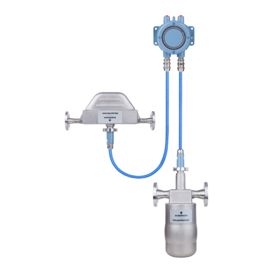
Emerson Micro Motion LNG Series Manuals
Manuals and User Guides for Emerson Micro Motion LNG Series. We have
1
Emerson Micro Motion LNG Series manual available for free PDF download: Configuration And Use Manual
Emerson Micro Motion LNG Series Configuration And Use Manual (100 pages)
Brand:
Emerson
| Category:
Measuring Instruments
| Size: 2.1 MB
Table of Contents
Table of Contents
3
Getting Started
7
Chapter 1 Before You Begin
9
About this Manual
9
Meter Model Codes
9
Communications Tools and Protocols
10
Additional Documentation
10
Chapter 2 Quick Start
13
Power up the Meter
13
Check Meter Status
13
Make a Startup Connection to the Transmitter
14
Characterize the Flowmeter (if Required)
14
Sensor Tags
15
Density Calibration Parameters (D1, D2, K1, K2, FD, TC)
15
Verify Mass Flow Measurement
15
Verify the Zero
15
Verify the Zero Using Prolink III
16
Terminology Used with Zero Verification and Zero Calibration
17
Part II Configuration and Commissioning
19
Chapter 3 Introduction to Configuration and Commissioning
21
Default Values and Ranges
21
Disable Write-Protection on the Transmitter Configuration
21
Restore the Factory Configuration
21
Chapter 4 Configure Process Measurement
23
Configure Mass Flow Measurement
23
Configure Mass Flow Measurement Unit
23
Configure Flow Damping
25
Configure Mass Flow Cutoff
26
Configure Volume Flow Measurement for Liquid Applications
27
Configure Volume Flow Type for Liquid Applications
27
Configure Volume Flow Measurement Unit for Liquid Applications
27
Configure Volume Flow Cutoff
30
Configure Gas Standard Volume (GSV) Flow Measurement
30
Configure Volume Flow Type for Gas Applications
31
Configure Standard Gas Density
31
Configure Gas Standard Volume Flow Measurement Unit
32
Configure Gas Standard Volume Flow Cutoff
34
Configure Flow Direction
34
Options for Flow Direction
35
Configure Density Measurement
36
Configure Density Measurement Unit
36
Configure Two-Phase Flow Parameters
37
Configure Density Damping
39
Configure Density Cutoff
40
Configure Temperature Measurement
40
Configure Temperature Measurement Unit
40
Configure Temperature Damping
41
Chapter 5 Configure Device Options and Preferences
43
Configure Response Time Parameters
43
Configure Calculation Speed (Response Time)
43
Configure Alert Handling
44
Configure Fault Timeout
44
Configure Status Alert Severity
44
Configure Informational Parameters
46
Configure the Sensor Index
46
Configure the RTD Cable Length
47
Configure Sensor Serial Number
47
Configure Sensor Material
47
Configure Sensor Liner Material
48
Configure Sensor Flange Type
48
Configure Descriptor
49
Configure Message
49
Configure Date
49
Chapter 6 Integrate the Meter with the Control System
51
Configure Events
51
Configure an Enhanced Event
51
Configure Digital Communications
52
Configure Modbus/Rs-485 Communications
53
Configure RS-485 Terminals
54
Configure Digital Communications Fault Action
55
Chapter 7 Complete the Configuration
57
Back up Transmitter Configuration
57
Enable Write-Protection on the Transmitter Configuration
57
Part III Operations, Maintenance, and Troubleshooting
59
Chapter 8 Transmitter Operation
61
Custody Transfer
61
Record the Process Variables
61
View Process Variables
62
View Process Variables and Other Data Using Prolink III
62
View Transmitter Status Using the Status LED
62
View and Acknowledge Status Alerts
63
View and Acknowledge Alerts Using Prolink III
63
Alert Data in Transmitter Memory
64
Read Totalizer and Inventory Values
65
Start and Stop Totalizers and Inventories
65
Reset Totalizers
66
Reset Inventories
66
Chapter 9 Measurement Support
67
Options for Measurement Support
67
Zero the Meter
67
Zero the Meter Using Prolink III
67
Record the Zeros
69
Validate the Meter
69
Alternate Method for Calculating the Meter Factor for Volume Flow
71
Perform a (Standard) D1 and D2 Density Calibration
71
Perform a D1 and D2 Density Calibration Using Prolink III
72
Chapter 10 Troubleshooting
75
Status LED States
75
Status Alerts, Causes, and Recommendations
76
Flow Measurement Problems
81
Density Measurement Problems
83
Temperature Measurement Problems
84
Check Power Supply Wiring
84
Check Grounding
85
Check for Radio Frequency Interference (RFI)
85
Check for Two-Phase Flow (Slug Flow)
86
Check the Drive Gain
86
Collect Drive Gain Data
87
Check the Pickoff Voltage
87
Collect Pickoff Voltage Data
88
Check for Internal Electrical Problems
88
Check the Sensor Coils
89
Appendix A Using Prolink III with the Transmitter
91
Connect with Prolink III
91
Connection Types Supported by Prolink III
91
Connect with Prolink III to the Service Port
91
Connect with Prolink III to the RS-485 Port
92
Appendix B Default Values and Ranges
95
Default Values and Ranges
95
Advertisement
Advertisement
Related Products
Emerson Micro Motion MVD Direct Connect
Emerson Micro Motion SGM
Emerson Micro Motion TA Series
Emerson Micro Motion Viscomaster
Emerson Micro Motion SGM Series
Emerson Micro Motion SGM*****D Series
Emerson Micro Motion SGM*****C Series
Emerson Micro Motion SGM*****B Series
Emerson Micro Motion SGM mA
Emerson Micro Motion SGM DO
Emerson Categories
Controller
Control Unit
Transmitter
Measuring Instruments
Fan
More Emerson Manuals
Login
Sign In
OR
Sign in with Facebook
Sign in with Google
Upload manual
Upload from disk
Upload from URL