
Subscribe to Our Youtube Channel
Related Manuals for SCHUNK DPZ-plus Series


Summary of Contents for SCHUNK DPZ-plus Series
- Page 1 Translation of the Original Manual Assembly and Operating Manual DPZ-plus Sealed 3-Finger Centric Gripper...
- Page 2 Imprint Copyright: This manual is protected by copyright. The author is SCHUNK GmbH & Co. KG. All rights reserved. Any reproduction, processing, distribution (making available to third parties), translation or other usage - even excerpts - of the manual is especially prohibited and requires our written approval.
-
Page 3: Table Of Contents
Table of Contents Table of Contents General........................ 6 About this manual .................... 6 1.1.1 Presentation of Warning Labels ............... 7 1.1.2 Applicable documents ................ 7 1.1.3 Sizes ...................... 7 1.1.4 Variants..................... 8 Warranty ...................... 8 Scope of delivery .................... 8 Accessories ...................... 9 1.4.1 Seal kits..................... 9 1.4.2 Spare parts packages ................ 10 Basic safety notes .................... 11 Intended use....................... - Page 4 Table of Contents 5.2.2 Pneumatic connection................ 25 Installing the ventilation connection/air purge connection ....... 26 Installing the sensors .................. 29 5.4.1 Overview of sensors ................ 29 5.4.2 Switch-off hysteresis for magnetic switches .......... 30 5.4.3 Setting dimensions ................. 30 5.4.4 Mounting MMS 22 magnetic switch............ 31 5.4.5 Mounting MMS 22-PI1 programmable magnetic switch...... 32 5.4.6 Mounting programmable MMS 22-PI2 magnetic switch...... 33 5.4.7 Mounting programmable MMS 22-P 22 magnetic switch...... 34...
- Page 5 Table of Contents Translation of original declaration of incorporation .......... 73 Annex to Declaration of Incorporation............... 74 25.00 | DPZ-plus | Assembly and Operating Manual | en | 389035...
-
Page 6: General
General 1 General 1.1 About this manual This manual contains important information for a safe and appropriate use of the product. This manual is an integral part of the product and must be kept accessible for the personnel at all times. Before starting work, the personnel must have read and understood this operating manual. -
Page 7: Presentation Of Warning Labels
• For ATEX versions: Supplementary sheet "Installation and operating instructions - EX" * The documents marked with an asterisk (*) can be downloaded on our homepage schunk.com 1.1.3 Sizes This operating manual applies to the following sizes: • DPZ-plus 40 •... -
Page 8: Variants
General 1.1.4 Variants This operating manual applies to the following variations: • DPZ-plus without gripping force maintenance • DPZ-plus with gripping force maintenance "O.D. gripping" (AS) • DPZ-plus with gripping force maintenance "I.D. gripping" (IS) • DPZ-plus force intensification (KVZ) •... -
Page 9: Accessories
General 1.4 Accessories A wide range of accessories are available for this product For information regarding which accessory articles can be used with the corresponding product variants, see catalog data sheet. The product has been redesigned as of 2020. The modified successor version is directly interchangeable with the previous version and replaces it. -
Page 10: Spare Parts Packages
Spare parts packages allow for the maintenance and repair of individual components. For information on the range of the spare parts packages, see www.schunk.com > Service. The following spare parts packages are available for this product: • Spare part package "Sealing kit"... -
Page 11: Basic Safety Notes
Use of unauthorized spare parts Using unauthorized spare parts can endanger personnel and damage the product or cause it to malfunction. • Use only original spare parts or spares authorized by SCHUNK. 25.00 | DPZ-plus | Assembly and Operating Manual | en | 389035... -
Page 12: Gripper Fingers
Basic safety notes 2.5 Gripper fingers Requirements for the gripper fingers Stored energy within the product creates the risk of serious injuries and significant property damage. • Arrange the gripper fingers in a way that the product reaches either the position "open" or "closed" in a de-energized state. •... -
Page 13: Personal Protective Equipment
Basic safety notes 2.8 Personal protective equipment Use of personal protective equipment Personal protective equipment serves to protect staff against danger which may interfere with their health or safety at work. • When working on and with the product, observe the occupational health and safety regulations and wear the required personal protective equipment. -
Page 14: Transport
Basic safety notes 2.10 Transport Handling during transport Incorrect handling during transport may impair the product's safety and cause serious injuries and considerable material damage. • When handling heavy weights, use lifting equipment to lift the product and transport it by appropriate means. •... -
Page 15: Fundamental Dangers
Basic safety notes 2.13 Fundamental dangers General • Observe safety distances. • Never deactivate safety devices. • Before commissioning the product, take appropriate protective measures to secure the danger zone. • Disconnect power sources before installation, modification, maintenance, or calibration. Ensure that no residual energy remains in the system. -
Page 16: Protection Against Dangerous Movements
Basic safety notes 2.13.3 Protection against dangerous movements Unexpected movements Residual energy in the system may cause serious injuries while working with the product. • Switch off the energy supply, ensure that no residual energy remains and secure against inadvertent reactivation. •... -
Page 17: Notes On Particular Risks
Basic safety notes 2.14 Notes on particular risks DANGER Risk of fatal injury from suspended loads! Falling loads can cause serious injuries and even death. Stand clear of suspended loads and do not step within their • swiveling range. Never move loads without supervision. •... - Page 18 Secure the end positions of the product with SCHUNK SDV-P • pressure maintenance valves. 25.00 | DPZ-plus | Assembly and Operating Manual | en | 389035...
-
Page 19: Technical Data
* For use in dirty ambient conditions (e.g. sprayed water, vapors, abrasion or processing dust) SCHUNK offers corresponding product options as standard. SCHUNK also offers customized solutions for special applications in dirty ambient conditions. More technical data is included in the catalog data sheet. -
Page 20: Design And Description
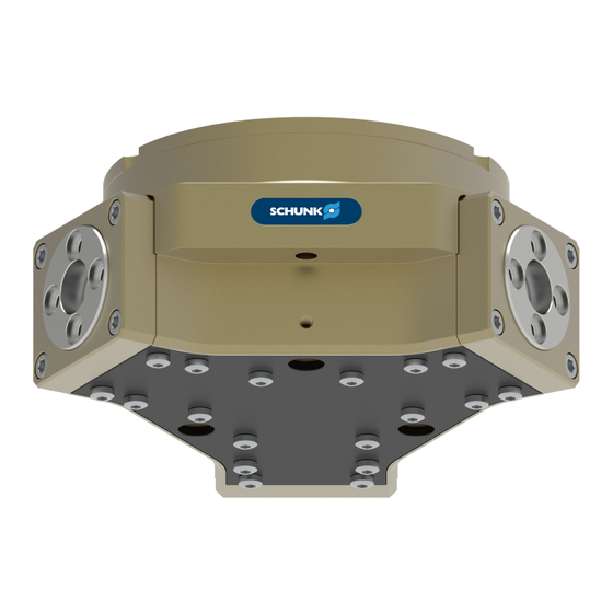
Design and description 4 Design and description 4.1 Design Sealed 3-finger centric gripper Housing Base jaw Compressed air main connection Air purge connection 4.2 Description Sealed 3-finger central gripper with high gripping force and high maximum moments due to multi-tooth guidance. 25.00 | DPZ-plus | Assembly and Operating Manual | en | 389035... -
Page 21: Assembly
Assembly 5 Assembly 5.1 Installing and connecting DANGER Danger of explosion in potentially explosive areas! Observe supplementary sheet for products with explosion- • resistant versions "DPZ-plus -...-EX". WARNING Risk of injury due to unexpected movements! If the power supply is switched on or residual energy remains in the system, components can move unexpectedly and cause serious injuries. -
Page 22: Mechanical Connection
Assembly Screw the product to the machine/system, Ø Mechanical connection 23]. When mounting from the rear: use cylindrical pins for fixing ✓ the product in place. If necessary, use appropriate connection elements (adapter ✓ plates). Observe requirements for adapter plate, ✓... - Page 23 Assembly 5.2 Connections 5.2.1 Mechanical connection The values apply to the whole mounting surface to which the Evenness of the product is mounted. mounting surface Requirements for evenness of the mounting surface (Dimensions in mm) Edge length Permissible unevenness < 100 <...
- Page 24 Assembly Connections at the base jaws Connections at the base jaws Item Mounting 80 100 125 160 200 Thread in base jaws M2.5 M3 M4 M5 M5 M6 M8 M12 Max. depth of engagement from locating surface [mm] Centering sleeve Ø...
-
Page 25: Pneumatic Connection
Assembly 5.2.2 Pneumatic connection NOTE • Observe the requirements for the compressed air supply, Technical data 19]. • In case of compressed air loss (cutting off the energy line), the components lose their dynamic effects and do not remain in a secure position. -
Page 26: Installing The Ventilation Connection/Air Purge Connection
Assembly 5.3 Installing the ventilation connection/air purge connection CAUTION Material damage due to incorrect connection! If the product is only operated with the two main air connections, neither correct functioning nor permanent tightness can be guaranteed. This can result in damage to the product. The product can only be operated if either a ventilation hose •... - Page 27 Assembly Installing the ventilation connection The ventilation line is designed to compensate for changes in volume inside the gripper due to gripper movement. It ensures no vacuums are created inside the gripper and that no dirt is thus sucked into the gripper. NOTE Make sure the ventilation line is assembled in a clean environment so that no dirt or liquid can be sucked into the...
- Page 28 Assembly Actuation with air purge Air purge actuation plan The use of air purge changes the gripping forces. Air purge pressure reduces the gripping force on closing and increases it on opening. Changes in gripping forces that arise due to air purge DPZ-plus Air purge pressure 0.2 bar...
-
Page 29: Installing The Sensors
– The assembly and operating manual and catalog datasheet are included in the scope of delivery for the sensors and are available at schunk.com. • Information on handling sensors is available at schunk.com or from SCHUNK contact persons. 5.4.1 Overview of sensors... -
Page 30: Switch-Off Hysteresis For Magnetic Switches
Assembly 5.4.2 Switch-off hysteresis for magnetic switches Sensors MMS 22, MMS-P 22, MMS 22-PI1 and MMS 22-PI2 The smallest detectable difference in stroke is defined in the following table: The smallest detectable difference in stroke based on the nominal stroke For grippers with X mm Min. -
Page 31: Mounting Mms 22 Magnetic Switch
Assembly 5.4.4 Mounting MMS 22 magnetic switch CAUTION Risk of damage to the sensor during assembly! Observe the maximal tightening torque. • Positioning the magnetic switches Position "Gripper open" or "Part gripped (I.D. gripping)" Bring product in the position to be set. Ø... -
Page 32: Mounting Mms 22-Pi1 Programmable Magnetic Switch
Assembly 5.4.5 Mounting MMS 22-PI1 programmable magnetic switch CAUTION Risk of damage to the sensor during assembly! Observe the maximal tightening torque. • NOTE If there is no T-nut available, slide the sensor according to dimension I1 into the groove (2), Setting dimensions 30]. -
Page 33: Mounting Programmable Mms 22-Pi2 Magnetic Switch
Assembly 5.4.6 Mounting programmable MMS 22-PI2 magnetic switch CAUTION Risk of damage to the sensor during assembly! Observe the maximal tightening torque. • NOTE If there is no T-nut available, slide the sensor according to dimension I1 into the groove (2), Setting dimensions 30]. -
Page 34: Mounting Programmable Mms 22-P 22 Magnetic Switch
Assembly 5.4.7 Mounting programmable MMS 22-P 22 magnetic switch CAUTION Risk of damage to the sensor during assembly! Observe the maximal tightening torque. • NOTE If there is no T-nut available, slide the sensor according to dimension I1 into the groove (2), Setting dimensions 30]. -
Page 35: Mounting Reed Switch Rms 22
Assembly 5.4.8 Mounting reed switch RMS 22 Position "Gripper open" or "Part gripped (I.D. gripping)" Bring product in the position to be set. Ø If necessary remove T-nut (3). Ø Turn the sensor 1 (1) into the groove (2). Ø OR: Slide the sensor 1 (1) into the groove (2) until the sensor 1 (1) stops at the end of the groove. -
Page 36: Mounting Fms Force-Measuring Jaw
Operating Instructions. NOTE Intermediate jaws (ZBA) and force-measuring jaws (FMS) are available from SCHUNK as accessories. When ordering, make sure that a size offset is formed between the intermediate and force- measuring jaws, so that the force-measuring jaws are always one size smaller than the gripper. -
Page 37: Troubleshooting
Unused air connections open. Close unused air connections. Flow control valve closed. Open the flow control valve. Component part defective. Replace component or send it to SCHUNK for repair. 25.00 | DPZ-plus | Assembly and Operating Manual | en | 389035... -
Page 38: The Product Is Not Executing The Complete Stroke
Check the evenness of the mounting surface. Mechanical connection 23] Component part defective. Replace component or send it to SCHUNK for repair. Air purge set too high (> 0.5 bar). Reduce air purge (max. 0.5 bar). 6.3 Product is opening or closing abruptly... -
Page 39: Product Does Not Achieve The Opening And Closing Times
If, despite optimum air connections, the opening and closing times specified in the catalogue are not achieved, SCHUNK recommends the use of quick-air-vent- valves directly at the product. 6.6 Programmable magnetic switches not switching as desired... -
Page 40: Maintenance
Maintenance 7 Maintenance 7.1 Notes DANGER Danger of explosion in potentially explosive areas! Observe supplementary sheet for products with explosion- • resistant versions "DPZ-plus -...-EX". WARNING Risk of burns through contact with hot surfaces! Surfaces of components can heat up severely during operation. Skin contact with hot surfaces causes severe burns to the skin. -
Page 41: Threadlocker
Remove all lubrication nipples after greasing and seal! • NOTE Previous version only: Do not grease the gasket (14), Assembly drawing 65]. SCHUNK recommends the lubricants listed. Interface Lubricant Metallic sliding surfaces Molykote BR 2 plus All seals Renolit HLT 2... -
Page 42: Disassembly And Assembly (Previous Version)
Maintenance 7.5 Disassembly and assembly (previous version) 7.5.1 Variant without maintenance of gripping force (previous version) Position of the item numbers Assembly drawing 65] Disassembling Remove the compressed air hose. Ø If necessary, remove the pressure piece, see insert "Installation Ø... - Page 43 Maintenance Assembling Push the base jaw (2/7) into the housing (1), observing the Ø correct installation position. Insert the piston (3/8) into the housing (1) from above. Ø Position the base jaws (2/7) so that the piston (3/8) can be Ø...
-
Page 44: Variant With "O.d. Gripping" Maintenance Of Gripping Force (Previous Version)
Maintenance 7.5.2 Variant with "O.D. gripping" maintenance of gripping force (previous version) Position of the item numbers Assembly drawing 65] WARNING Risk of injury due to spring forces! The cover is under spring tension. Carefully disassemble the product. • Disassembling Remove the compressed air hose. - Page 45 Maintenance Assembling NOTE Tighten all screws to the required torque, Tightening torque for screws 64] For sizes 40–100, the cylinder piston must be installed using assembly device 1, and for sizes 125–200 using assembly device 1 and 2, Assembly device for cylinder piston with maintenance of gripping force 64].
- Page 46 Maintenance Size 40–100 Fastening elements for assembly device DPZ-plus Item Designation Assembly device 1 Screw M3 x 20 M3 x 25 M5 x 30 M6 x 35 M6 x 40 DIN ISO 4762 Cylindrical pin 2m6 x 6 3m6 x 8 5m6 x 5m6 x 5m6 x Install and grease device 1 (100).
- Page 47 Maintenance NOTE Do not damage the sealing lips of the seal (36) with the intermediate jaw (13). Put on the side cover (12), making sure the installation position Ø is correct. Do not screw the screw (42) completely into the cover (12). The Ø...
- Page 48 Maintenance Size 125–200 with two assembly devices Fastening elements for assembly device DPZ-plus Item Designation Assembly device 1 Screw DIN ISO 4762 M8 x 50 M8 x 60 M10 x 70 Cylindrical pin 6m6 x 16 6m6 x 16 8m6 x 20 Assembly device 1 Screw DIN ISO 4762 M8 x 40 M8 x 45 M10 x 50...
- Page 49 Maintenance Do not screw the screw (42) completely into the cover (12). The Ø gap between the side cover (12) and the housing (1) should be approximately divided in half. Allow the gripper to run for about 20 cycles so that the side Ø...
-
Page 50: Variant With "I.d. Gripping" Maintenance Of Gripping Force (Previous Version)
Maintenance 7.5.3 Variant with "I.D. gripping" maintenance of gripping force (previous version) Position of the item numbers Assembly drawing 65] WARNING Risk of injury due to spring forces! The cover is under spring tension. Carefully disassemble the product. • Disassembling NOTE Tighten all screws with the required tightening torque., Tightening torque for screws... - Page 51 Maintenance Assembling Push the base jaw (2/7) into the housing (1), observing the Ø correct installation position. Position the base jaws (2/7) so that the piston (3/8) can be Ø pushed into the base jaws (2/7) without any problems. NOTE Do not damage the sealing lips of the seal (30) while pushing in the cylinder piston.
-
Page 52: Variant With "Force Intensifying Cylinder" (Kvz) (Previous Version)
Maintenance 7.5.4 Variant with "force intensifying cylinder" (KVZ) (previous version) Position of the item numbers Assembly drawing 65] Disassembling Remove the compressed air hose. Ø If necessary, remove the pressure piece, see insert "Installation Ø instructions - pressure piece". Unfasten and remove the screws (47). Ø... -
Page 53: Position Of The Plast-O-Seal (Previous Version)
Maintenance Push the intermediate housing (65) over the cylinder piston (6). Ø Fasten the cover (4) with screws (41). Ø NOTE The product must be in the "closed" position to prevent the gasket (14) from being clamped in the housing (1) by the intermediate jaw (13). -
Page 54: Disassembly And Assembly (Successor Version)
Maintenance 7.6 Disassembly and assembly (successor version) 7.6.1 Variant without maintenance of gripping force (successor version) Position of the item numbers, Assembly drawing 65] Disassembling Remove the compressed air hose. Ø If necessary, remove the pressure piece, see insert "Installation Ø... - Page 55 Maintenance Insert the cylinder piston (61) from below into the housing (1), Ø observing the correct installation position. Screw in the screw (40). Ø Insert seal (32) / O-rings (32/34) into the cover (4). Ø Fasten the cover (4) with screws (41). Ø...
-
Page 56: Variant With "O.d. Gripping" Maintenance Of Gripping Force (Successor Version)
Maintenance 7.6.2 Variant with "O.D. gripping" maintenance of gripping force (successor version) Position of the item numbers, Assembly drawing 65] WARNING Risk of injury due to spring forces! The cover is under spring tension. Carefully disassemble the product. • Disassembling Remove the compressed air hose. - Page 57 Maintenance Assembling NOTE Tighten all screws to the required torque, Tightening torque for screws 64] For sizes 40–100, the cylinder piston must be installed using assembly device 1, and for sizes 125–200 using assembly device 1 and 2, Assembly device for cylinder piston with maintenance of gripping force 64].
- Page 58 Maintenance Size 125–200 with two assembly devices Fastening elements for assembly device Item Designation DPZ-plus Assembly device 1 Screw DIN ISO 4762 M8 x 50 M8 x 60 M10 x 70 Cylindrical pin 6m6 x 16 6m6 x 16 8m6 x 20 Assembly device 2 Screw DIN ISO 4762 M8 x 40 M8 x 45 M10 x 50...
- Page 59 Maintenance NOTE Do not damage the sealing lips of the seal (36) with the intermediate jaw (13). Put on the side cover (12), making sure the installation position Ø is correct. Do not screw the screw (42) completely into the cover (12). The Ø...
-
Page 60: Variant With "I.d. Gripping" Maintenance Of Gripping Force (Successor Version)
Maintenance 7.6.3 Variant with "I.D. gripping" maintenance of gripping force (successor version) Position of the item numbers, Assembly drawing 65] WARNING Risk of injury due to spring forces! The cover is under spring tension. Carefully disassemble the product. • Disassembling Remove the compressed air hose. - Page 61 Maintenance Assembling NOTE Tighten all screws with the required tightening torque., Tightening torque for screws 64]. Push the base jaw (2/7) into the housing (1), observing the Ø correct installation position. Position the base jaws (2/7) so that the piston (3/8) can be Ø...
-
Page 62: Variant With "Force Intensifying Cylinder" (Kvz) (Successor Version)
Maintenance 7.6.4 Variant with "force intensifying cylinder" (KVZ) (successor version) Position of the item numbers, Assembly drawing 65] Disassembling Remove the compressed air hose. Ø If necessary, remove the pressure piece, see insert "Installation Ø instructions - pressure piece". Unfasten and remove the screws (47). Ø... - Page 63 Maintenance NOTE Do not damage the sealing lips of the seal (30) while pushing in the cylinder piston. Insert the cylinder piston (61) from below into the housing (1), Ø observing the correct installation position. Install the intermediate piston (66). Ø...
-
Page 64: Tightening Torque For Screws
Maintenance 7.7 Tightening torque for screws Position of the item numbers, Assembly drawing 65] Tightening torque in Nm Size Item 0.45 1.35 1.35 57.5 0.45 7.8 Assembly device for cylinder piston with maintenance of gripping force Cylinder piston assembly device 25.00 | DPZ-plus | Assembly and Operating Manual | en | 389035... -
Page 65: Assembly Drawing
Maintenance Cylinder piston assembly device - dimensions in mm Ø A Ø C Ø d1 Ø d2 Ø d3 Ø d6 Ø d7 Type DPZ-plus 40 27.5 DPZ-plus 50 DPZ-plus 64 DPZ-plus 80 DPZ-plus 100 DPZ-plus 125 94.5 94.5 DPZ-plus 160 40 127.5 127.5 DPZ-plus 200 M10 M10... - Page 66 Maintenance Assembly of the variants O.D. gripping/I.D. gripping/without maintenance of gripping force (previous version) Wearing part, replace during maintenance. Included in the seal kit. Seal kit can only be ordered completely. Positions are adapted to each other and can not be replaced by the customer.
- Page 67 Maintenance Assembly of the variants O.D. gripping/I.D. gripping/without maintenance of gripping force (successor version) Wearing part, replace during maintenance. Included in the seal kit. Seal kit can only be ordered completely. Positions are adapted to each other and can not be replaced by the customer.
- Page 68 Maintenance Assembly of the variant with force intensification cylinder (previous version / successor version) * Wearing part, replace during maintenance. Included in the seal kit. Seal kit can only be ordered completely. Gripper variants with force intensification cylinders are not permitted for use in explosion-protected applications (EX).
-
Page 69: Appendix
Appendix 8 Appendix 8.1 Differentiation between the previous version and the successor version The product has been redesigned as of 2020. The modified successor version is directly interchangeable with the previous version and replaces it. The difference between the two versions lies exclusively in the design and is therefore only relevant for spare parts such as the sealing kit. - Page 70 Appendix Ident number Ident number DPZ-plus Previous version Successor version 64-1 304411 1316280 64-1-AS 304413 1316283 64-1-AS-EX 305242 1315457 64-1-AS-V 39304413 1321312 64-1-EX 305240 1315399 64-1-IS 304415 1316286 64-1-IS-EX 305244 1315465 64-1-IS-V 39304415 1321318 64-1-KVZ 304417 1316281 64-1-V 39304411 1321310 64-2 304412 1316282...
- Page 71 Appendix Ident number Ident number DPZ-plus Previous version Successor version 100-1 304431 1316296 100-1-AS 304433 1316299 100-1-AS-EX 305262 1315494 100-1-AS-V 1321646 1321332 100-1-EX 305260 1315491 100-1-IS 304435 1316301 100-1-IS-EX 305264 1315505 100-1-IS-V 1321336 100-1-V 39304431 1321329 100-2 304432 1316297 100-2-AS 304434 1316300 100-2-AS-EX...
- Page 72 Appendix Ident number Ident number DPZ-plus Previous version Successor version 160-1 304451 1316310 160-1-AS 304453 1316313 160-1-AS-EX 305282 1315531 160-1-AS-V 39304453 1321351 160-1-EX 305280 1315526 160-1-IS 304455 1316315 160-1-IS-EX 305284 1315544 160-1-IS-V 1321354 160-1-V 39304451 1321347 160-2 304452 1316312 160-2-AS 304454 1316314 160-2-AS-EX...
-
Page 73: Translation Of Original Declaration Of Incorporation
9 Translation of original declaration of incorporation in terms of the Directive 2006/42/EG, Annex II, Part 1.B of the European Parliament and of the Council on machinery. Manufacturer/ SCHUNK GmbH & Co. KG Clamping and gripping technology Distributor Bahnhofstr. 106 - 134 D-74348 Lauffen/Neckar... -
Page 74: Annex To Declaration Of Incorporation
Translation of original declaration of incorporation 9.1 Annex to Declaration of Incorporation according 2006/42/EG, Annex II, No. 1 B 1.Description of the essential health and safety requirements pursuant to 2006/42/EC, Annex I that are applicable and that have been fulfilled with: Product designation Sealed 3-finger centric gripper Type designation DPZ-plus... - Page 75 Translation of original declaration of incorporation Protection against mechanical hazards 1.3.7 Risks related to moving parts 1.3.8 Choice of protection against risks arising from moving parts 1.3.8.1 Moving transmission parts 1.3.8.2 Moving parts involved in the process 1.3.9 Risks of uncontrolled movements Required characteristics of guards and protective devices 1.4.1 General requirements...
- Page 76 Translation of original declaration of incorporation Information 1.7.1 Information and warnings on the machinery 1.7.1.1 Information and information devices 1.7.1.2 Warning devices 1.7.2 Warning of residual risks 1.7.3 Marking of machinery 1.7.4 Instructions 1.7.4.1 General principles for the drafting of instructions 1.7.4.2 Contents of the instructions 1.7.4.3...
Need help?
Do you have a question about the DPZ-plus Series and is the answer not in the manual?
Questions and answers