
Related Manuals for SCHUNK VERO-S NSL3


Summary of Contents for SCHUNK VERO-S NSL3
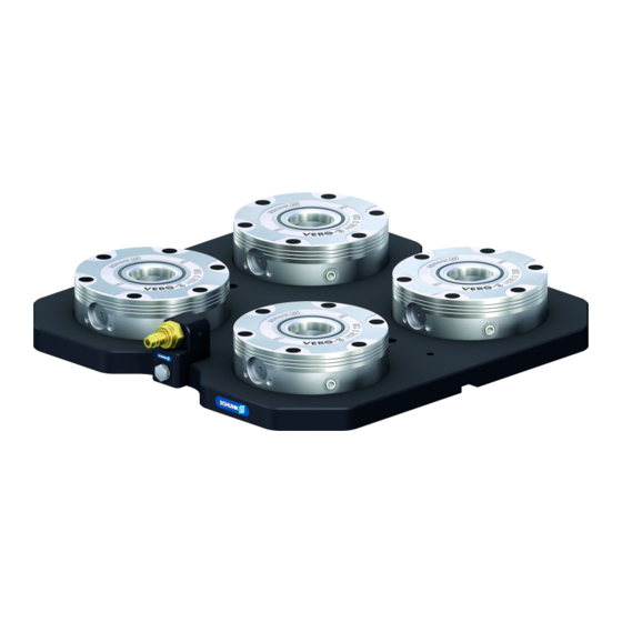
- Page 1 Translation of Original Operating Manual VERO-S quick-change pallet system NSL3 Assembly and Operating Manual...
- Page 2 Imprint Imprint Copyright: This manual is protected by copyright. The author is SCHUNK GmbH & Co. KG. All rights reserved. Technical changes: We reserve the right to make alterations for the purpose of technical improvement. Document number: 1155408 Version: 03.00 | 11/03/2022 | en...
-
Page 3: Table Of Contents
Table of Contents Table of Contents General........................ 5 About this manual .................... 5 1.1.1 Presentation of Warning Labels ............... 5 1.1.2 Applicable documents ................ 5 1.1.3 Sizes ...................... 6 Warranty ...................... 6 Scope of delivery .................... 7 Accessories ...................... 7 Basic safety notes .................... 8 Intended use...................... - Page 4 Table of Contents Function ......................... 34 Connections on the clamping station .............. 34 Unlocking connection .................. 34 TURBO connection (with NSL 3-V1).............. 35 VERO-S connecting strip ASL1-G1/8", ASL2-G1/8" (optional) ...... 36 Cone seal KVS3 (optional)................... 37 Monitoring system AFS3 138 MMS (optional) ........... 38 Monitoring system AFS3 138 PMI (optional)............
-
Page 5: General
• General terms of business * • Catalog data sheet of the purchased product * The documents marked with an asterisk (*) can be downloaded on our homepage www.schunk.com. 03.00 | NSL3 | VERO-S quick-change pallet system | en | 1155408... -
Page 6: Sizes
General 1.1.3 Sizes This operating manual applies to the following sizes: Clamping station • NSL3 150-V1-T • NSL3 200 • NSL3 200-V1-T • NSL3 300-200 • NSL3 400 • NSL3 600 • NSL3 800 1.2 Warranty The warranty period is 24 months after delivery date from factory or 500 000 cycles*, if it is used as intended, under the following conditions: •... -
Page 7: Scope Of Delivery
General 1.3 Scope of delivery The scope of delivery includes • Clamping station in the version ordered • Accessory kit and separate packing units NSL3 150-V1-T: 2 sealing rings G1/8", 2 sealing nipples G1/8", 2 pneumatic plug-in connections for nominal hose width Ø 4 NSL3 200;... -
Page 8: Basic Safety Notes
Use of unauthorized spare parts Using unauthorized spare parts can endanger personnel and damage the product or cause it to malfunction. • Use only original spare parts or spares authorized by SCHUNK. 03.00 | NSL3 | VERO-S quick-change pallet system | en | 1155408... -
Page 9: Environmental And Operating Conditions
Basic safety notes 2.5 Environmental and operating conditions Required ambient conditions and operating conditions Incorrect ambient and operating conditions can make the product unsafe, leading to the risk of serious injuries, considerable material damage and/or a significant reduction to the product's life span. •... -
Page 10: Personal Protective Equipment
Basic safety notes Qualified personnel Due to its technical training, knowledge and experience, qualified personnel is able to perform the delegated tasks, recognize and avoid possible dangers and knows the relevant standards and regulations. Instructed person Instructed persons were instructed by the operator about the delegated tasks and possible dangers due to improper behaviour. -
Page 11: Transport
• Dispose of the clamping device's metal parts as scrap metal. Alternatively, you can return the clamping device to SCHUNK for proper disposal. 03.00 | NSL3 | VERO-S quick-change pallet system | en | 1155408... -
Page 12: Fundamental Dangers
Basic safety notes 2.12 Fundamental dangers General • Observe safety distances. • Never deactivate safety devices. • Before commissioning the product, take appropriate protective measures to secure the danger zone. • Disconnect power sources before installation, modification, maintenance, or calibration. Ensure that no residual energy remains in the system. -
Page 13: Protection Against Dangerous Movements
Basic safety notes 2.12.3 Protection against dangerous movements Unexpected movements Residual energy in the system may cause serious injuries while working with the product. • Switch off the energy supply, ensure that no residual energy remains and secure against inadvertent reactivation. •... - Page 14 Basic safety notes WARNING Risk of injury due to falling device, pallet or workpiece if the clamping pin locking is loosened from the clamping bolt mounting erroneously or as a result of negligence. During operation, erroneous or negligent loosening of the •...
- Page 15 Basic safety notes CAUTION Risk of injury due to compressed air hoses coming loose when connected improperly. Use check valves or safety switches. • Take appropriate protective measures to secure the danger • zone. CAUTION There is a risk of limbs being crushed by moving parts during manual loading and unloading and during the clamping procedure.
-
Page 16: Technical Data
Technical data 3 Technical data Type Holding force* Fmax ** FmaxT *** Weight designation (M10 / M12) Total pull Total pull down force down force without with turbo turbo NSL3 150-V1-T 1323568 35 kN / 50 kN 8 kN 28 kN 7.0 kg NSL3 200 1323569... -
Page 17: Assembly
Assembly 4 Assembly 4.1 General Installation Notes Pre-assembly measures Lift the quick-change pallet system carefully out of the packaging (e.g. using suitable lifting equipment). For clamping stations NSL3 400 or higher, eye bolts are supplied for transporting the clamping station. The eye bolts are to be mounted into the transport threads on the base plate and then removed after assembly. -
Page 18: Aligning The Clamping Station
Assembly 4.2 Aligning the clamping station The clamping station can be aligned with loose T-nuts along an aligning groove on the machine table. At least two T-nuts offset lengthwise are provided and their size is matched to the aligning groove on the machine table. The T-nuts are not included in the scope of delivery of the clamping station. - Page 19 Assembly Even height of the clamping modules Even height of the clamping modules inside a clamping station is only ensured when in a clamped state. Set-up is performed by means of individually inserted holes or optionally available clamp blanks. The clamping station or the clamp blanks must be fastened using adequately dimensioned mounting screws in accordance with DIN EN ISO 4762 starting with thread size M10.
-
Page 20: Nsl3 150-V1-T
Assembly Clamping range NSL3 150-V1-T NSL3 200 / NSL3 NSL3 400 NSL3 600 NSL3 800 200-V1-T A, I B, C, J, K B, E, J, M B, D, G, J, L, O B, D, F, H, J, L, N, P Note The clamping range of the NSL3 300-200 is based on the clamping scheme of the NSL3 400. - Page 21 Assembly unobstructed along the bottom of the base plate. Make sure that the clamping station with the base plate is not located in the water bath. For this reason, make sure the coolant in the machine compartment has completely drained when actuating the air connections.
- Page 22 Assembly positional orientation of the clamping pallet or for the use of a clamping membrane type SPM plus 138. The NSL3 150-V1-T has two G 1/8" connectors for separate functions. One air connection for unlocking and one air connection for the turbo function. Supply occurs either via the pneumatic plug connections G1/8"...
-
Page 23: Nsl3 200
Assembly occurs either via two pneumatic plug connections G1/8" 6/4 or two sealing nipples for locking couplings type NW 7.4 (accessory). The clamping station can be retrofitted at the connection points using a separately available connecting strip (accessory). Reduced material thickness in marked areas Bore holes permitted in... -
Page 24: Nsl3 300-200
Assembly grooves each. These are intended for positional orientation when using single clamping pallets types PAL-S, PAL-A or clamping membranes for workpiece clamping type SPM plus 138. The clamping station can be retrofitted at the connection points using a 2x connection strip (accessory). Reduced material thickness in marked areas Bore holes permitted in... - Page 25 Assembly Reduced material thickness in marked areas Bore holes permitted in shaded areas NSL3 300-200 4.3.5 NSL3 400 The clamping station can be clamped directly onto the machine table via screws. Permitted areas for appropriate bore holes can be found in the attached bore hole drawings. Optionally, BRR 50 clamp banks can be purchased.
- Page 26 Assembly screw. Supply occurs either via a pneumatic plug connection G1/8" 8/6 or a sealing nipple for locking couplings type NW 7.4 (accessory). The clamping station can be retrofitted at the connection points using a separately available connecting strip (accessory). Reduced material thickness in marked areas...
- Page 27 Assembly simultaneously unlocking all six clamping points. The air supply can be connected to either the front or the back of the clamping station. The opposing connection point is closed with a locking screw. Supply occurs either via a pneumatic plug connection G1/8" 8/6 or a sealing nipple (accessory) for locking couplings type NW 7.4 (accessory).
- Page 28 Assembly 4.3.7 NSL3 800 The clamping station can be clamped directly onto the machine table via screws. Permitted areas for appropriate bore holes can be found in the attached bore hole drawings. Optionally, BRR 50 clamp banks can be purchased. There are already 6 mounting holes at a distance of 200 x 200.
- Page 29 Assembly Reduced material thickness in marked areas Bore holes permitted in shaded areas Reduced material thickness in marked areas NSL3 800 03.00 | NSL3 | VERO-S quick-change pallet system | en | 1155408...
- Page 30 If clamping pins are used outside of SCHUNK pallets, for example in customer-specific devices or workpieces, the outer diameter of the part to be clamped must be large enough to completely cover the plan sealing ring on the top of all quick-change pallet systems involved in the clamping function.
- Page 31 Assembly Tolerances and installation conditions Type ID no. SPA 40 0471151 > 12 > 17 > 15 > 20 >12 SPB 40 0471152 > 12 > 17 > 15 > 20 >12 SPC 40 0471153 > 12 > 17 > 15 >...
-
Page 32: Clamping Pallets Pal-S, Pal-A (Optional)
The clamping pallets achieve highly accurate repeat accuracy in combination with the VERO-S NSL3 clamping station. When using single clamping pallets, these can be placed in a position-oriented and non-rotating fashion on a single NSE3 138- V1 clamping module in combination with the NSL3-V1 clamping station. -
Page 33: Screw Tightening Torques
Assembly VERO-S clamping pallets Two fitting grooves on the NSE3 138-V1 Indexing pins for positional clamping module for angular positioning orientation at 0° and 90° NSL3 150-V1-T with single clamping pallet 4.6 Screw tightening torques Tightening torques for mounting clamping pins to the workpiece or to the clamping pallet. -
Page 34: Function
Function 5 Function The VERO-S NSL3 clamping station guarantees rapid changing of VERO-S clamping pallets, devices or workpieces in the machine room with a high level of repeat accuracy. In the VERO-S quick- change pallet modules, the clamping pallet is positioned and locked via the related VERO-S clamping pin. -
Page 35: Turbo Connection (With Nsl 3-V1)
Function slides of the quick-change pallet module moves into the closed position. Exchanging the clamping pallet is not possible with clamping modules that are not locked. WARNING Risk of injury due to clamping pallet falling from the clamping station if the unlocking connection is not scheduled pressurized according to schedule. -
Page 36: Vero-S Connecting Strip Asl1-G1/8", Asl2-G1/8" (Optional)
Function 5.4 VERO-S connecting strip ASL1-G1/8", ASL2-G1/8" (optional) Upon customer request, a VERO-S terminal block can be mounted to the clamping station in order to facilitate access to the air supply point. The connecting strip is equipped with an elevated connection point with a size NW 7.4 sealing nipple. -
Page 37: Cone Seal Kvs3 (Optional)
Via the cone seal, the quick-change pallet system can be protected against the penetration of coolant and chips into the change interface. Note The clamping stations VERO-S NSL3 are not fitted as standard to a connection position for the exhaust function of the clamping modules. Note To install the cone seal in a VERO-S NSE3, the plug fitted must first be removed from the change interface. -
Page 38: Monitoring System Afs3 138 Mms (Optional)
Function KVS3 cone seal Remove the plug installed in the clamping KVS3 cone seal module before installing retrofitted in the cone seal clamping module NSL3 clamping station retrofitted with cone seal 5.6 Monitoring system AFS3 138 MMS (optional) The AFS3 138 MMS monitoring system can be mounted to the NSL3 clamping station upon customer request. -
Page 39: Monitoring System Afs3 138 Pmi (Optional)
Function 5.7 Monitoring system AFS3 138 PMI (optional) The AFS3 138 PMI monitoring system can be mounted to the NSL3 clamping station upon customer request. The monitoring system can evaluate whether the operating states is "TENSIONED" or "UNLOCKED" and transmit this data to the machine control system. -
Page 40: Media Feed-Through Vero-S Mdn 3-2 (Optional)
Function 5.8 Media feed-through VERO-S MDN 3-2 (optional) As an option, the NSL3 clamping station can be enhanced with the VERO-S MDN 3-2 media feed-through. The media feed-through is intended for transmitting liquid and gaseous media from the NSL3 clamping station to the clamping pallet. The compact design of the media feed-through allows for variable positioning on the base plate of the clamping station. -
Page 41: Operation
In this case, the system must be inspected and damaged parts must be replaced immediately. Only original SCHUNK spare parts may be used! WARNING Risk of injury due to losing pallets or workpieces in the case of incorrect actuation caused by incorrect operation. -
Page 42: Maintenance And Care
Risk of injury and risk of damage to the clamping module when opening the housing cover. If the clamping module has to be disassembled, send the module to SCHUNK for repair. The covers of the clamping modules are spring preloaded and may only be removed by trained specialist personnel. The... -
Page 43: Leak Test
Maintenance and care • Check the supply hose line to the pressure supply of the clamping station for damage at regular intervals. The supply hose line must be of the appropriate nominal hose width and be completely inserted into the air connections and securely clamped. -
Page 44: Troubleshooting
Defective air connections Check air supply Pressure below minimum Check operating pressure (min. 5 bar) A component is broken (e.g. due to Replace the module or send it to SCHUNK for overloading) repair Excess tensile load on clamping pins Reduce support weight 8.2 The clamping areas do not unlock perfectly... -
Page 45: Parts Lists
Parts lists 9 Parts lists 9.1 Part lists NSL3 150-V1-T (ID no. 1323568) Item Designation Quantity Base plate NSE3 138-V1 Set-screw Locking screw Sealing ring G1/8" Sealing nipple G1/8" Pneumatic screw-in union G1/8" 6/4 Cylindrical clamp blanks BRR 50 Optional NSL3 200 (ID no. - Page 46 Parts lists Cylindrical clamp blanks BRR 50 Optional NSL3 300-200 (ID no. 1323571) Item Designation Quantity Base plate Air duct strip NSE3 138-V1 O-ring O-ring Countersunk screw Set-screw Locking screw Sealing ring G1/8" Sealing nipple G1/8" Pneumatic screw-in union G1/8" 6/4 Cylindrical clamp blanks BRR 50 Optional NSL3 400 (ID no.
- Page 47 Parts lists Sealing ring G1/8" Sealing nipple G1/8" Pneumatic screw-in union G1/8" 8/6 Cylindrical clamp blanks BRR 50 Optional Eye bolt, M8 NSL3 800 (ID no. 1323575) Item Designation Quantity Base plate Air duct strip NSE3 138 O-ring O-ring Countersunk screw Locking screw Sealing ring G1/8"...
-
Page 48: Assembly Drawings
Assembly Drawings 10 Assembly Drawings 10.1 NSL3 with NSE3 138-V1 quick-change pallet module Included with VERO-S NSE3 138-V1 With VERO-S NSE3 138-V1 Included with VERO-S NSE3 138-V1 * installed on delivery ** included in accessory pack *** alternative plug connection in accessory pack NSL3 with NSE3 138-V1 quick-change pallet module 03.00 | NSL3 | VERO-S quick-change pallet system | en | 1155408... -
Page 49: Nsl3
Assembly Drawings 10.2 NSL3 Included with VERO-S NSE3 138 Included with VERO-S NSE3 138 * installed on delivery ** included in accessory pack *** alternative plug connection in accessory pack **** in NSL3 400, NSL3 600, NSL3 800 NSL3 03.00 | NSL3 | VERO-S quick-change pallet system | en | 1155408... -
Page 50: Declaration Of Incorporation
11 Declaration of Incorporation in terms of the Directive 2006/42/EG, Annex II, Part 1.B of the European Parliament and of the Council on machinery. Manufacturer/ H.-D. SCHUNK GmbH & Co. Spanntechnik KG Distributor Lothringer Str. 23 D-88512 Mengen We hereby declare that on the date of the declaration the following partly completed machine complied with all basic safety and health regulations found in the directive 2006/42/EC of the European Parliament and of the Council on machinery. -
Page 51: Appendix On Declaration Of Incorporation, As Per 2006/42/Ec, Annex Ii, No. 1 B
Appendix on Declaration of Incorporation, as per 2006/42/EC, annex II, No. 1 B 12 Appendix on Declaration of Incorporation, as per 2006/42/EC, annex II, No. 1 B 1. Description of the basic safety and health protection requirements, as per 2006/42/EC, Annex I, that apply to and are fulfilled for the scope of the partly completed machinery: Product designation Quick-Change Pallet System VERO-S Type designation... - Page 52 Appendix on Declaration of Incorporation, as per 2006/42/EC, annex II, No. 1 B Protection against mechanical hazards 1.3.6 Risks related to variations in operating conditions 1.3.7 Risks related to moving parts 1.3.8 Choice of protection against risks arising from moving parts 1.3.8.1 Moving transmission parts 1.3.8.2 Moving parts involved in the process 1.3.9...
- Page 53 Appendix on Declaration of Incorporation, as per 2006/42/EC, annex II, No. 1 B Information 1.7.1 Information and warnings on the machinery 1.7.1.1 Information and information devices 1.7.1.2 Warning devices 1.7.2 Warning of residual risks 1.7.3 Marking of machinery 1.7.4 Instructions 1.7.4.1 General principles for the drafting of instructions 1.7.4.2 Contents of the instructions 1.7.4.3 Sales literature...
- Page 56 Translation of Original Operating Manual H.-D. SCHUNK GmbH & Co. Spanntechnik KG Lothringer Str. 23 D-88512 Mengen Tel. +49–7572-7614-0 Fax +49-7572-7614-1099 info@de.schunk.com schunk.com Folgen Sie uns I Follow us...
Need help?
Do you have a question about the VERO-S NSL3 and is the answer not in the manual?
Questions and answers