
Related Manuals for Stealth Products ST-TWBM480-QL-Q


Summary of Contents for Stealth Products ST-TWBM480-QL-Q
- Page 1 Mounting Hardware OWNERS MANUAL ST-TWBM480-QL-Q & ST-TWBM480-CJ-Q Stealth’s User and Installation Manual for the Flip-Down Hardware with Joystick Mounts...
- Page 2 Customer Satisfaction Stealth Products strives for 100% customer satisfaction. Your complete satisfaction is important. Please contact us with feedback or suggested changes that will help improve the quality and usability of our products. You may reach us at: Stealth Products, LLC...
- Page 3 Important Information Important Information! All persons responsible for fitting, adjustment, and daily use of the devices discussed in these instructions must be familiar with and understand all safety aspects of the devices mentioned. In order for our products to be used successfully, you must: ...
-
Page 4: Introduction
They also contain important safety and maintenance information. For further assistance, or more advanced applications, please contact your supplier or Stealth Products at (512) 715-9995 or toll free 1-800-965-9229. Always keep the operating instructions in a safe place so they may be referenced as necessary. -
Page 5: Warranty
Warranty Our products are designed, manufactured, and produced to the highest of standards. If any defect in material or workmanship is found, Stealth Products will repair or replace the product at our discretion. Any implied warranty, including the implied warranties of merchantability and fitness for a particular purpose, shall not extend beyond the duration of this warranty. -
Page 6: Table Of Contents
7.0 Product Warnings ....................vii 8.0 Design & Function ....................1 8.1 Intended Use ..........................1 9.0 Parts and Accessories ..................... 2 9.1 ST-TWBM480-QL-Q/ST-TWBM480-CJ-Q ................2 9.2 Tools ..............................3 9.3 Torque Specs ..........................3 10.0 Installation Instructions ..................4 10.1 Replacing the FDM380 ...................... -
Page 7: Warning Labels
SAFETY necessary. Limited Liability Stealth Products, LLC accepts no liability for personal injury or damage to property that may arise from the failure of the user or other persons to follow the recommendations, warnings, and instructions in this manual. Stealth Products does not hold responsibility for final integration of final assembly of product to end user. -
Page 8: Product Warnings
Product Warnings The following safety precautions should be taken when adjusting the flip-down joystick mount hardware: CAUTION Ensure the red flip-down sleeve freely rotates. If the flip-down sleeve does not rotate, the hardware will not work properly. CAUTION When tightening screws, turn loosely until the screws stop, then tighten one quarter turn more. -
Page 9: Design & Function
Design and Function Intended Use The ST-TWBM480-QL-Q/ST-TWBM480-CJ-Q hardware utilizes Stealth’s link style hardware to provide limitless adjustment. Multiple planes of adjustment allow critical adjustment for the joystick mounts. Separate links isolate adjustment planes and angles, while individual link adjustment achieves the most complex support solutions, making the positioning for your joystick simple. -
Page 10: Parts And Accessories
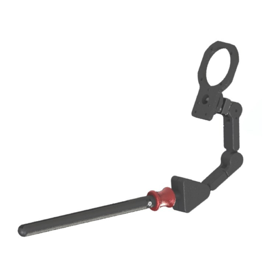
3” Offset Link Inline Link 3” Inline Link Ball Mount 17mm Headrest Ball Q-Logic Plate Q-Logic Interface Plate 3 Hole Ring 3 Hole Ring Interface Plate Curtis Joystick Interface Plate ST-TWBM480-CJ-Q The ST-TWBM480-CJ-Q includes the same components as the ST-TWBM480-QL-Q. -
Page 11: Tools
Tools, anti-seize, and Blue Medium Strength Liquid Loctite Series 242 are not provided. Torque Specs Screws Torque Specification 1/4 x 20 x 1” FHS 140in-lbs 10-32 x 1/4” SS 40in-lbs 10-32 x 5/8” SHS 90in-lbs M5 Shoulder Screw 6.9nM *Torque specifications for ST-TWBM480-QL-Q & ST-TWBM480-CJ-Q are the same. -
Page 12: Installation Instructions
Step 5: Tighten the screw and locknut on the vertical bar. There should be minimum lateral movement with the assembly. *Instructions for replacing FDM380 are the same for the ST-TWBM480-QL-Q & ST-TWBM480-CJ-Q CAUTION Ensure that all screws are tightened evenly on the hardware. Threads can strip out and cause damage to the hardware if not tightened properly. -
Page 13: Flip-Down Mount
An audible ‘click’ should occur, indicating that the hardware is locked back into place. * ST-TWBM480-CJ-Q shown. Follow the same instructions for the ST-TWBM480-QL-Q. CAUTION Ensure the red flip-down sleeve freely rotates 360°. If the flip-down sleeve does not rotate, the hardware will not work properly. -
Page 14: Link Adjustment
Installation Instructions 10.0 Link Adjustment 10.3 Step 1: Loosen the set screw on the offset link with a 4mm T-Handle, but do not remove. Loosen the flat head screw from the offset link with a 4mm T-Handle. Step 2: Make any adjustments to the links necessary. Tighten all flat head screws and ensure all the links are in the desired position. -
Page 15: First Time Use
Explain and show the customer how you have executed the installation, and explain the function. Have the user test the position of the ST-TWBM480-QL-Q/ST-TWBM480-CJ-Q hardware: Is the hardware in the proper position for the client? ... -
Page 16: Maintenance
Maintenance 12.0 Maintenance 12.1 All parts should be checked on a regular basis and repaired, if necessary, by a service technician. Discontinue use after identifying loose or broken components. Periodically check the flip-down sleeve. Test that it engages properly and makes an audible ‘click’... - Page 17 NOTES 13.0...
- Page 18 NOTES 13.0...
- Page 19 NOTES 13.0...
- Page 20 Stealth Products, LLC. • info@stealthproducts.com • www.stealthproducts.com +1(800) 965-9229 | +1(512) 715-9995 | 104 John Kelly Drive, Burnet TX 78611 P139D510 Revision Date 2019-12-17...
Need help?
Do you have a question about the ST-TWBM480-QL-Q and is the answer not in the manual?
Questions and answers