Table of Contents
Advertisement
Quick Links
Advertisement
Table of Contents

Related Manuals for KVH Industries TracVision TV10


Summary of Contents for KVH Industries TracVision TV10
- Page 1 TracVision T V10 ® Installation Guide...
-
Page 2: Table Of Contents
KVH, TracVision, and the unique light-colored dome with dark contrasting baseplate (Reg. No. 2,864,752) are registered trademarks of KVH Industries, Inc. All other trademarks are property of their respective companies. The information in this document is subject to change without notice. No company shall be liable for errors contained herein. - Page 3 Important Safety Information This icon indicates a danger, warning, or caution notice. Be sure to read these carefully to avoid injury. WARNING Risk of Electric Shock To avoid electric shock, do not open the TV-Hub chassis enclosure. There are no user-serviceable parts inside.
-
Page 4: Inspect Parts And Get Tools
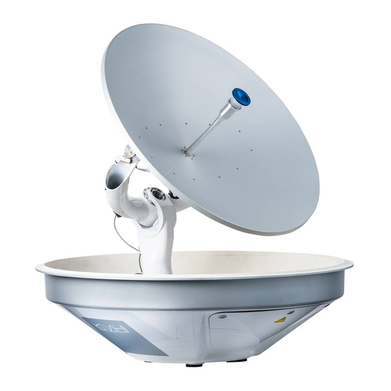
Inspect Parts and Get Tools Before you begin, follow these steps to ensure Figure 1: TracVision TV10 System Components you have everything needed to complete the Antenna installation. IMPORTANT! Always lift the antenna by the baseplate and never by the radome or any portion of the internal antenna assembly (see Figure 1). -
Page 5: Plan The Antenna Installation
Plan the Antenna Installation Before you begin, consider the following antenna Figure 3: Blockage from Obstruction installation guidelines. -20° to 80° Look Angle IMPORTANT! Be sure to follow the guidelines below. Damage caused by an improper installation is not covered under KVH warranty. Blocked! •... - Page 6 Continued Plan the Antenna Installation • Make sure the mounting surface is wide Figure 5: Antenna Dimensions enough to accommodate the antenna’s base Side View (see Figure 5). Also make sure it is flat, level (within ±1°), strong enough to support the antenna’s weight (198 lbs (89.8 kg)) and rigid enough to prevent antenna vibration.
- Page 7 Continued Plan the Antenna Installation Pedestal Structural Requirements Figure 6: Pedestal Dimensions If a pedestal is going to be used, it must meet the Pedestal following minimum requirements. Refer to (Side View) Figure 5. Pedestal 3.28 ft 6.56 ft 9.84 ft Height Tube OD 9.0"...
-
Page 8: Plan The Tv-Hub Installation
Plan the TV-Hub Installation Consider the following TV-Hub installation Figure 7: TV-Hub Dimensions guidelines. Horizontal • Select a mounting location in a dry, well- Orientation ventilated area belowdecks away from any LED Lights heat sources or salt spray. 3.23" • Do not install the TV-Hub in an area (8.2 cm) surrounded by metal or near any electrical 1.73"... -
Page 9: Prepare The Antenna Site
Prepare the Antenna Site Once you have identified a suitable antenna Figure 8: Antenna Mounting Holes Layout mounting site, according to the guidelines Ø.63" (Ø16 mm) provided in “Plan the Antenna Installation” on Face Vessel Bow Antenna Mounting page 4, follow these steps to drill the mounting Hole (x4) holes and cable access hole to prepare the site for installation. -
Page 10: Prepare The Rf Cables
Prepare the RF Cables Determine the necessary type of RF cable(s) and Figure 9: Number of RF Coax Cables to Connect to Antenna connectors you need for any RF cables that are LNB Type # of Receivers RF Cables required in addition to what is supplied in the antenna kit (see Figure 9 and Figure 10). -
Page 11: Rig/Hoist The Antenna
Rig/Hoist the Antenna Follow these steps to remove the shipping bolts Figure 11: Service Hatch and Hardware securing the antenna to the pallet and safely rig the antenna for crane hoisting. IMPORTANT! The antenna’s radome and baseplate have painted surfaces. Be sure to take protective measures to avoid gouging or scratching the antenna during the rigging operation. -
Page 12: Wire The Antenna
Wire the Antenna Follow these steps to connect the antenna RF Figure 14: Foam Seal on Base of Antenna cable(s) to the antenna. Antenna Baseplate (Bottom View) a. Clean and dry the bottom of the antenna baseplate (see Figure 14). Foam Seal b. - Page 13 Continued Wire the Antenna Make sure the RF cable is hand-tightened all Figure 17: Cable Cover/Screws/Washers the way into the connector. Then tighten it with a 7/16" torque wrench to 20 in-lbs, or a #6-32 Captive Screw and Washer (x6) 7/16"...
-
Page 14: Mount The Antenna
Mount the Antenna Follow these steps to mount the antenna. Figure 19: Forward Arrow in Antenna Baseplate a. Using a 7/16" socket/ratchet or nut driver, unlock the three hex latches securing each of the antenna’s service hatches (see Figure 11 on page 10). - Page 15 Continued Mount the Antenna h. Disconnect the crane rigging. Figure 21: Lift Bracket Removal Using a 5/32" hex key and 1/2" open-end wrench, remove the eight screws, flat washers, and lock nuts securing the four lift brackets to the antenna (see Figure 21). Remove the brackets and hardware and set 1/4"-20 x 1.5"...
-
Page 16: Mount The Tv-Hub
Mount the TV-Hub Follow these steps to install the TV-Hub inside Figure 23: TV-Hub Mounting Template the vessel. Front of TV-Hub IMPORTANT! 7.93" Keyhole Before continuing, locate the serial number on (20.1 cm) 2 x Ø 0.13" the bottom of the TV-Hub and record it on the (Ø... -
Page 17: Wire The Antenna To The Tv-Hub
Wire the Antenna to the TV-Hub Follow these steps to connect the antenna to the Figure 25: TV-Hub Antenna Connection TV-Hub. a. Fill half of the inner body of the RG-11 RF1 cable connector, that you will be connecting to the TV-Hub, with the supplied silicone grease. -
Page 18: Wire The Receivers
Wire the Receivers The steps for connecting the customer’s Figure 26: TV-Hub Receiver Connections receiver(s) to the TracVision system and setting them up depends upon the customer’s satellite TV service (see Figure 26). TV-Hub NOTE: KVH’s TracVision Configuration Wizard, FUSE Wi-Fi DSWM available at www.kvh.com/tvseriesconfigurator,... - Page 19 Continued Wire the Receivers Linear Wiring Figure 27: Wiring 1 Linear Receiver Follow these steps to connect linear receivers to the TracVision system. NOTE: The linear universal quad LNB is required. Connecting 1-4 Linear Receivers a. Connect an RF cable from the “Receiver” jack on the TV-Hub to the “Satellite In”...
- Page 20 Continued Wire the Receivers Connecting 5 or More Linear Receivers Figure 29: Wiring 5+ Linear Receivers a. Connect an RF cable from the “Receiver” jack on the TV-Hub to the “18V” jack on the multiswitch (see Figure 29). NOTE: If the desired satellite TV service is limited to channels carried on high-band transponders, connect the RF cable from the TV-Hub to one of the “22KHz”...
- Page 21 Continued Wire the Receivers DIRECTV – SWM Wiring Figure 30: Wiring 1 DIRECTV SWM Receiver Follow these steps to connect DIRECTV SWM receivers to the TracVision system. NOTE: The stacked circular LNB (supplied in kit) is required. Refer to “Installing a Circular LNB” on page Connecting 1 SWM Receiver TV-Hub...
- Page 22 Continued Wire the Receivers Connecting 9-13 SWM Receivers (13 Tuners Max) Figure 32: Wiring Up to 13 DIRECTV SWM Devices To connect more than eight SWM devices, connect TV-Hub an RF cable from the “DSWM” jack on the DSWM FUSE TV-Hub to the “SWM”...
- Page 23 Continued Wire the Receivers DIRECTV Latin America Wiring Figure 33: Wiring 1 DIRECTV Latin America Receiver Follow these steps to connect DIRECTV Latin America receivers to the TracVision system. NOTE: The DIRECTV L.A. circular LNB is required (KVH part no. 72-0906). Connecting 1 Receiver Connect an RF cable from the “Receiver”...
- Page 24 Continued Wire the Receivers Tri-Americas Wiring Figure 35: Wiring a Tri-Americas System Follow these steps to connect both DIRECTV Latin America and DIRECTV U.S. receivers to the TracVision system (see Figure 35). NOTE: The Tri-Americas LNB is required (KVH part no.
- Page 25 Continued Wire the Receivers DISH Network and Bell TV Wiring Figure 36: Wiring 1 DISH/Bell Receiver Follow these steps to connect DISH Network or Bell TV receivers to the TracVision system NOTE: The stacked circular LNB (supplied in kit) is required. Refer to “Installing a Circular LNB”...
- Page 26 Continued Wire the Receivers Sky Mexico Wiring Figure 39: Wiring 1 Sky Mexico Receiver Follow these steps to connect Sky Mexico receivers to the TracVision system. NOTE: The Sky Mexico LNB is required (KVH part no. 72-0908). IMPORTANT! These instructions assume you will connect to the 79°W satellite (Sky Mexico 1) for service TV-Hub and are not applicable for service obtained...
-
Page 27: Connect A Nmea Device
Connect a NMEA Device Optional At the customer’s request, you can connect a NMEA device to the TV-Hub, allowing the antenna to use its GNSS position and heading Figure 41: TV-Hub NMEA Connections data to speed up satellite acquisition. The current TV-Hub NMEA position and heading will also be displayed on... -
Page 28: Connect Power
Connect Power Before connecting power, be sure the vessel is Figure 44: Grounding Block Example properly grounded in accordance with marine standards. Grounding Requirements Proper grounding of the TracVision system to ship’s ground is mandatory for electromagnetic compatibility (EMC) and safety regulatory compliance. - Page 29 Continued Connect Power Connect Power to the System Figure 45: TracVision System Power NOTE: When powering up a SWM configuration, Connecting to AC Power apply power to all other system components before powering up the receivers and DVRs (tuners are assigned SWM channels during startup).
-
Page 30: Turn On The System
Turn On the System Follow these steps to turn on the system for the Figure 46: TV-Hub Power Switch first time. a. Ensure the antenna has a clear, unobstructed view of the sky. Power Switch b. Press the power switch on the rear panel of FUSE Wi-Fi NMEA 2000... -
Page 31: Access The Web Interface
Access the Web Interface Follow the steps for either option below to access Figure 48: Wi-Fi Connection the TV-Hub’s web interface. Option 1: Using the Wireless Connection a. Select the TVHub-<TV-Hub serial number> network from your device’s Wi-Fi settings to connect to the TV-Hub (see Figure 48). -
Page 32: Connect To An Onboard Network
Connect to an Onboard Network Optional Connecting the TV-Hub to an onboard local area network (LAN) is required if any of the following Figure 50: TV-Hub Network Connections conditions apply: • One or more IP AutoSwitches are installed to enable automatic satellite switching (Linear/ DISH Network/Bell TV only) TV-Hub •... -
Page 33: Secure The Wi-Fi Connection
Secure the Wi-Fi Connection By default, the TV-Hub’s wireless settings are Figure 53: TV-Hub Security and Password Setting configured for the following: • Wireless Mode: AP (Access Point) • SSID: TV-Hub-<TV-Hub serial number> • IP Address: 172.16.0.1 • Security Mode: Off KVH strongly advises that you select the WPA_PSK security mode as shown in Figure 53 and assign a unique password to prevent... -
Page 34: Set Up The System
Set Up the System The Setup Wizard appears upon initial startup to Figure 54: Setup Wizard Welcome Page step you through system configuration (see Figure 54). Before you begin to set up the system: • Know the service provider and associated satellite(s) •... - Page 35 Continued Set Up the System Setup Wizard Figure 56: Preset Satellite Groups System configuration continues by prompting Service Satellites (A-B-C-D) you to enter information or perform certain tasks, as necessary. For example: Linear Europe 1: Hotbird, Astra1, Astra2S, Astra3 • Enter installer and vessel information Europe 2: •...
- Page 36 Continued Set Up the System Linear Receiver Setup for Automatic Figure 57: Linear Receiver DiSEqC Settings (Example) Switching TV-Hub Web Interface Receiver Setup For automatic switching to work properly using Ku_HOTBIRD 6,7A,8 LNB Type 09750/10600 the DiSEqC communications protocol, set up LNB Power 13/18V linear receivers for the same satellites installed in...
-
Page 37: Educate The Customer
Educate the Customer Before you leave the vessel, test the system. Fill Figure 58: Satellite Switching Selection on Home Page out the Installation Checklist (see the Welcome Kit) and return it to KVH. Refer to the instructions on the form. Give the Welcome Kit to the customer, provide any passwords and static IP addresses you set up, and explain how to use the system. -
Page 38: Installing A Circular Lnb
Installing a Circular LNB Appendix Follow these instructions to modify the antenna for use with Bell TV, DISH Network, and DIRECTV SWM receivers by installing the Figure 61: Stacked Circular LNB supplied stacked circular LNB (Figure 61). Tools Required This procedure requires the following tools: •... - Page 39 Continued Installing a Circular LNB Remove the Linear Universal Quad LNB Figure 63: Linear Universal Quad LNB RF Cable Routing Follow the steps below to remove the linear RF3 RF2 universal quad LNB from the antenna system (see Figure 63). 1.
- Page 40 Continued Installing a Circular LNB Installing a Stacked Circular LNB Figure 66: Stacked Circular LNB RF Cable Routing Follow the steps below to install the stacked circular LNB in your antenna system (see Figure 66). Tie-wrap 1. Insert the new LNB fully into the choke feed and orient the LNB as shown.
- Page 41 Continued Installing a Circular LNB Registering the New LNB Figure 67: Technician Mode Follow the steps below to register the new LNB with the antenna. 1. Connect your computer or mobile device to the TV-Hub and access its web interface. Refer to “Access the Web Interface”...
-
Page 42: Installing An Ip Autoswitch
Installing an IP AutoSwitch Appendix Follow these steps to add an IP AutoSwitch (KVH part no. 72-0634) to each DISH Network, Bell TV, or linear receiver you want to be able to Figure 69: IP AutoSwitch control satellite selection in Automatic satellite switching mode. - Page 43 Continued Installing an IP AutoSwitch Wire the IP AutoSwitch Figure 71: IP AutoSwitch Connections The wiring of the IP AutoSwitch depends on the RF Input** RF Input** specific configuration. Refer to the wiring diagrams provided in “Wire the Receivers” on page 17 while following the general wiring steps below:...
- Page 44 Continued Installing an IP AutoSwitch Configure the IP AutoSwitch Figure 72: Add IP AutoSwitch Screen When performing system setup (see “Set Up the System” on page 33), follow these additional steps to configure the IP AutoSwitch. NOTE: KVH recommends that you run the Setup Wizard in the web interface whenever you change your system’s configuration by adding or removing devices.
- Page 45 Continued Installing an IP AutoSwitch Band/Polarization Control Figure 74: Band/Polarization Control Setting If your configuration consists of linear receivers connected via a multiswitch, and you installed one or more IP AutoSwitches, KVH recommends that you change the TV-Hub’s Band/Polarization Control setting to TV-Hub (see Figure 74). You can find this setting on the Advanced Settings page of the web interface (go to Settings >...
-
Page 46: Using A Directv Coax Network
Using a DIRECTV Coax Network Appendix In Automatic satellite switching mode, the TV-Hub can accept commands from the master Figure 76: DIRECTV Configuration SWM-compatible DIRECTV receiver to TV-Hub automatically switch between the 101W and DSWM Ethernet 119W satellites. The TV-Hub communicates with FUSE Wi-Fi NMEA 2000... - Page 47 Continued Using a DIRECTV Coax Network Additional Equipment for Older Receivers Figure 77: Additional Equipment for Older Receivers In addition to the DECA Broadband Kit, you might need to connect an additional device in- SWM Splitter line between the receiver and the SWM splitter, Receiver/DVR Models: H21, H22, H23, HR21, HR22, HR23 depending on the model (see Figure 77).
- Page 48 Continued Using a DIRECTV Coax Network Configuring the DIRECTV Receivers for Figure 78: IP Addressing for Automatic Switching (Example) Automatic Switching To establish communications between the TracVision system and each SWM-compatible TV-Hub DIRECTV receiver for automatic satellite FUSE Wi-Fi DSWM NMEA 2000 ETHERNET DC IN...
- Page 49 Continued Using a DIRECTV Coax Network Assigning Static IP Addresses to DIRECTV Receivers Figure 80: IP Address on a DIRECTV Receiver (Example) Once you have identified a valid static IP address WITHOUT an Onboard Network (No Router) range for the receivers, follow these steps to assign a unique static IP address within that range to each receiver.
- Page 50 Continued Using a DIRECTV Coax Network 10. Add the new receivers to the Figure 81: Adding a DIRECTV Receiver to the Autoswitch Page Autoswitch page of the web interface. Enter each receiver’s static IP address and assign it a friendly name (e.g., “Salon”) (see Figure 81).
- Page 51 REGULATORY COMPLIANCE European Union Compliance Hereby, KVH Industries, Inc. declares that the radio equipment type TracVision TV10 is in compliance with EMC Directive 2014/30/EU. For the full text of the EU Declaration of Conformity, go to www.kvh.com/euconformity. Federal Communications Commission Compliance The TracVision system complies with Class B of Part 15 of the FCC (Federal Communications Commission) rules for radiated and conducted emissions.
- Page 52 Directive 2014/53/EU; Part 2: Indoor unit Dynamic Range Only) Equipment applicability The TracVision TV10 is a system that provides TVRO (Television receive only) connectivity between a ship and satellite-based television broadcast services. The equipment is not intended for SOLAS applications.
- Page 54 KVH Industries A/S KVH Industries, Inc. KVH Industries Pte Ltd. EMEA Headquarters World Headquarters Asia-Pacific Headquarters Kokkedal, Denmark Middletown, RI U.S.A. Singapore Tel: +45 45 160 180 Fax: +45 45 160 181 Tel: +1 401 847 3327 Fax: +1 401 849 0045 Tel: +65 6513 0290 Fax: +65 6472 3469 Email: info@emea.kvh.com...
Need help?
Do you have a question about the TracVision TV10 and is the answer not in the manual?
Questions and answers