
Related Manuals for KVH Industries LF


Summary of Contents for KVH Industries LF
- Page 1 A Guide to TracVision LF/SF owner’s Installation Instructions • User’s Guide • Technical Manual • manual...
-
Page 2: Dish 500 Operation
(ECO # 6857) The following information applies to Revision D of the TracVision LF/SF Owner’s Manual (KVH Part Number 54-0194). The DISH 500 mode, in which the SAT SELECT button switches between the two DISH 500 satellites, has been changed to make it easier to use. -
Page 3: Resetting The System To Factory Default
IMPORTANT! Switch between satellites only while the vehicle is stationary or, if your system is a TracVision LF, while you are driving in a straight line. If you try to switch satellites while the vehicle is turning, the antenna may lock onto the wrong satellite. - Page 4 , and ExpressVu. This manual provides detailed instructions on the proper installation, use, and maintenance of your TracVision LF/SF system. Before using this manual, be sure to check the inside back cover for any addenda, which may detail changes to the manual’s information.
- Page 5 ® ® TracVision and KVH are registered trademarks of KVH Industries, Inc. ® DIRECTV is an official trademark of DIRECTV, a unit of GM Hughes Electronics Corporation. ™ DISH Network is an official trademark of EchoStar Communications Corporation. ExpressVu is a property of Bell ExpressVu, a wholly owned...
-
Page 6: Table Of Contents
Satellite Dish Operation ....... .2-13 Using Your TracVision LF/SF ..... .3-1 Turning On the System . - Page 7 4.1.2 Dew or Rain Pooling on Dome ...4-2 4.1.3 Satellite Signal Blocked ...4-2 4.1.4 Satellite Coverage Issue...4-3 4.1.5 Vehicle Turning During Startup (TracVision LF only)...4-3 4.1.6 Incorrect or Loose RF Connectors ...4-3 4.1.7 Type of Multiswitch Used ...4-3 4.1.8 Stationary Use Only (TracVision SF only) ...4-3 IRD Troubleshooting .
- Page 8 Field Replaceable Unit Procedures ......5-3 5.4.1 PCB Removal and Replacement...5-5 5.4.2 Antenna Gyro Assembly (TracVision LF only)...5-6 5.4.3 Antenna LNB Replacement ...5-8 Preparation for Shipment .
-
Page 9: Introduction
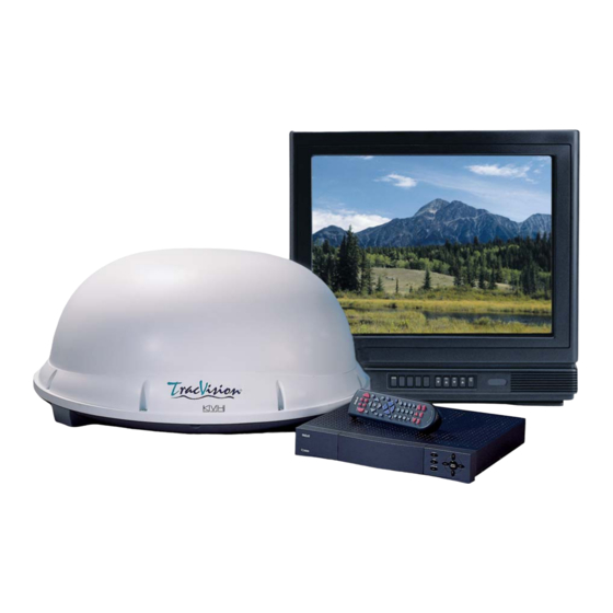
United States. TracVision LF/SF automatically identifies, locks onto, and receives signals from the appropriate satellite. TracVision SF is designed for stationary use only; TracVision LF works while your vehicle is at rest and in motion. System Overview A complete satellite TV system includes the TracVision LF/SF connected to an IRD (satellite TV receiver) and a television set. -
Page 10: Tracvision Lf/Sf Components
Materials Provided with TracVision LF/SF Table 1-1 lists the units, cables, and materials packed in the TracVision LF/SF package by name and KVH part number. Component Antenna Unit (TracVision LF) Antenna Unit (TracVision SF) RF Cable (28 ft)*... -
Page 11: Additional Materials Required For Tracvision Lf/Sf Use
1.3.1 Additional Materials Required for TracVision LF/SF Use To make full use of your new TracVision LF/SF and receive satellite TV, you will need to provide/purchase the following: • Television • Appropriate IRD for your selected satellite TV service 54-0194 Rev. D... -
Page 12: Installation
Installation TracVision LF/SF is designed for simple installation and setup. Just follow these easy steps: Step Choose the antenna location Mount the antenna unit Connect the system components Activate the IRD Check out the system Tools and Materials Required •... -
Page 13: Choosing The Best Location
A Guide to TracVision LF/SF Figure 2-1 Antenna Blockage Figure 2-2 Maximum Mounting Surface Slope Choosing the Best Location • Since the TracVision antenna requires a clear view of the southern sky to receive satellite signals, the ideal antenna site has an unobstructed view of the horizon/satellite all around. -
Page 14: Mounting The Antenna Unit
Mounting the Antenna Unit 1. Make sure that you have chosen a suitable mounting location based upon the guidelines in Section 2.1, “Choosing the Best Location.” 2. Remove the antenna unit from its shipping carton. 3. At the bottom of the antenna baseplate, cut the tie-wrap and pull it out of the baseplate. - Page 15 A Guide to TracVision LF/SF If the roof’s mounting surface is not perfectly flat as KVH recommends, make sure the baseplate does not warp when you attach the antenna’s mounting plates. Refer to Section 2.1, “Choosing the Best Location,” for further details.
-
Page 16: Connecting System Components
Locating the Switchplate Before running cables, you need to determine the location for the TracVision LF/SF switchplate. 1. The switchplate should be installed in a dry, flat location within reach of the cables that will connect to the antenna unit. -
Page 17: Connecting The Antenna To The Switchplate
A Guide to TracVision LF/SF Figure 2-7 Switchplate Connectors Switchplate Mounting Hole (1 of 2) KVH recommends the use of RG-6 or RG-11 (75 ohms) cable for RF wiring. Use of non-RG-6 or RG-11 (75 ohms) cables will result in degraded performance. - Page 18 Installing Two IRDs and TVs To connect a second TV and IRD to the TracVision LF/SF system, you must connect a second RF cable to the antenna’s RF2 connector (see Figure 2-6). Route the other end of the RF cable down into the vehicle and connect it directly to the second IRD.
-
Page 19: Sealing The Cable Access Hole
A Guide to TracVision LF/SF Figure 2-9 Installing the Clamshell Ventilator EchoStar IRDs cannot be connected to the switchplate due to incompatibility. Satellite selection must be done manually through the switchplate’s SAT SELECT button. 4. Terminate all unused output connectors with 75 ohm DC blocks (Channel Master #7184, Radio Shack #15-1259 or equivalent). -
Page 20: Connecting The Switchplate To Vehicle Power
2.3.5 Connecting the Switchplate to Vehicle Power The switchplate must be connected to a +12 VDC, 2.5-3.5 amp power supply to operate. 1. Disconnect vehicle power by removing the appropriate vehicle fuse. 2. Run a cable from vehicle’s power (11-16 VDC) out through the switchplate panel cutout. -
Page 21: Activating The Ird
Data Connection Turn on the IRD and press the switchplate’s POWER button to power up the TracVision LF/SF system. Observe messages on your TV screen to verify proper operation. Some messages originate in the IRD, others are generated in the TracVision LF/SF circuits. - Page 22 EL Motor Error Fault detected in elevation drive subassembly Ant Gyro Error Fault detected in antenna gyro assembly, OR (TracVision LF only) antenna gyro failed to initialize properly because vehicle was turning during the 60-second startup and initialization period following power-up...
-
Page 23: Checking Out The System Without An Ird Data Connection
A Guide to TracVision LF/SF Figure 2-10 Switchplate Maintenance Port Figure 2-11 PC Data Cable DB9 Connector 2-12 2.5.2 Checking Out the System Without an IRD Data Connection To ensure that the system is configured and operating properly, you will need to check the data provided in the system’s startup routine. -
Page 24: Configuring Tracvision Lf/Sf For Remote
The wiring option for the remote dish is very simple and should be installed when the TracVision LF/SF is installed. A high-quality “A/B switch” should be used to change from TracVision to remote antenna operation. The recommended wiring arrangement for remote dish operation is illustrated in Figure 2-12. -
Page 25: Using Your Tracvision Lf/Sf
Simply go to our web site at: footprint. Turning On the System The TracVision LF/SF system is easy to use. To turn on the TracVision LF/SF system, follow the steps below. 1. (TracVision SF only) Park your vehicle. - Page 26 3. Press the switchplate’s POWER button, as pictured in Figure 3-2. Power Button 4. (TracVision LF only) If the vehicle is moving, avoid turning for 60 seconds after turning on the antenna to allow the antenna gyro to initialize properly.
-
Page 27: Tracking The Correct Satellite
Satellite Selection.” 3.2.1 Using the IRD for Satellite Selection If your TracVision LF/SF is connected to an IRD’s low-speed data port, the antenna will automatically find and track the correct satellite based on the information it receives from the IRD. No user interaction is required. -
Page 28: The Status Indicator
If the vehicle moves after the TracVision LF/SF is turned off, the antenna unit will quickly carry out its normal initialization routine to reacquire the satellite when next powered on. -
Page 29: Dish 500 Operation
During this process, your television transmission will be frozen momentarily while the cable unwraps and the antenna reacquires the satellite. Conical Scan Tracking (TracVision LF only) The antenna control unit uses conical scanning to maintain peak signal strength to the receiver and to update the satellite’s position. -
Page 30: Switching Between Dish 500 Satellites
IMPORTANT! Switch between satellites only while the vehicle is stationary or, if your system is a TracVision LF, while you are driving in a straight line. If you try to switch satellites while the vehicle is turning, the antenna may lock onto the wrong satellite. -
Page 31: Troubleshooting
Causes and Remedies for Common Operational Issues There are a number of common issues that can affect the signal reception quality or the operation of the TracVision LF/SF. The following sections address these issues and potential solutions. 54-0194 Rev. D... -
Page 32: Blown Fuse Or Improper Wiring
Refer to Section 2.1, “Choosing the Best Location,” to make certain that the TracVision LF/SF unit is in the optimal location. Simply moving the vehicle to clear an external obstruction will also restore signal quality. -
Page 33: Satellite Coverage Issue
If the vehicle turns during the 60-second startup and initialization sequence that occurs immediately after turning on the power to the TracVision LF unit, the antenna gyro will record that variable motion as “standing still.” This may cause the antenna to track improperly. To solve this problem, turn the TracVision LF off for at least 10 seconds. -
Page 34: Ird Troubleshooting
A Guide to TracVision LF/SF The long-term fix, typically done at original system installation, is to install an Uninterruptible Power Supply (like those available for use with computer systems) on the IRD. Be sure to specify a UPS with adequate available current for all devices attached to it. -
Page 35: Failed Ird Status Check
IRD. Solution Check to be certain that the IRD and TracVision LF/SF are connected properly at the low-speed data port and that both are powered on. Refer to Section 2.3, “Connecting System Components,”... -
Page 36: Antenna Gyro And Lnb Faults
Antenna Gyro and LNB Faults Section 5, “Maintenance,” provides detailed instructions for authorized service personnel who may be required to replace TracVision LF/SF components. The TracVision SF does not include an antenna gyro. Computer Diagnostics TracVision LF/SF has been designed to provide diagnostic readouts viewed on the TV screen (DIRECTV only) or on a personal computer having an RS-232 serial communication port. - Page 37 • Parity: None • Stop bits: 1 • Flow control: None 3. Apply power to the TracVision LF/SF system and allow the system to complete full initialization. Data should be scrolling on the PC display to identify any system problems detected. If no data is seen, recheck your connections and the terminal software setup.
-
Page 38: Maintenance
Shipments received without an RMA number will be returned to you at your expense. Preventive Maintenance TracVision LF/SF requires minimal preventive maintenance. The following tasks are sufficient to maintain peak performance. Monthly •... -
Page 39: Replaceable Parts
CPU PCB Antenna Gyro (TracVision LF only) Antenna Gyro Gasket (TracVision LF only) System Fuse It is recommended that all other technical difficulties be resolved by returning the TracVision LF/SF unit to an authorized service provider. Part Number 02-0953-08 02-0953-07... -
Page 40: Field Replaceable Unit Procedures
The procedures refer to labeled items presented on the following diagrams. PCB Cover 3.15-amp Fuse Antenna Gyro (TracVision LF only) Linear Actuator 54-0194 Rev. D Always lift the antenna unit by the gray baseplate, never by the... - Page 41 A Guide to TracVision LF/SF Figure 5-3 Antenna Assembly TracVision LF only Antenna Gyro Cable Locking Nuts and Washers Antenna Gyro Antenna Gyro Gasket Figure 5-4 Rotating Plate Cable Clamp and Screw Antenna Gyro Cable (TracVision LF only) Reflector Bracket...
-
Page 42: Pcb Removal And Replacement
Figure 5-5 Removing the PCB Cover PCB Cover TracVision LF/SF is equipped with a 5x20 mm, 3.15-amp, 250 volt fast-blow fuse, which is mounted on the PCB. To access and replace the fuse, remove the PCB cover. -
Page 43: Antenna Gyro Assembly (Tracvision Lf Only)
A Guide to TracVision LF/SF Figure 5-6 PCB Connector Locations – Rear View Limit Switches Gyro (TracVision LF only) RF Connector RF Connector to IRD When replacing the PCB cover, be careful not to pinch any cables. Elevation Motor to LNB 7. - Page 44 4. Remove 6 pan head screws from the PCB cover flanges. 5. Remove the PCB cover. To get the necessary clearance, rotate the linear actuator up 90º while lifting the PCB cover – Fig. 5-5. 6. Remove the screw and clamp holding the cable to the rotating plate;...
-
Page 45: Antenna Lnb Replacement
A Guide to TracVision LF/SF When replacing the LNB, make certain to restore it to its original orientation, as shown in Figure 5-3. The CALLNB Function requires the antenna to be pointed directly at the satellite peak before performing this routine. Using the FINDSAT... - Page 46 8. Record the Cold Sky Average and the RFGAIN value reported in Step 7. ZAP<cr> 9. Type . The system will re-initialize using the new RFGAIN and RFOFFSET scale factors displayed following Step 7. 10. Wait for the system to perform the background noise calculation.
-
Page 47: Preparation For Shipment
A Guide to TracVision LF/SF When rotating the azimuth mechanism by hand, go slowly! Hitting the mechanical stops with excessive force will damage the azimuth limit switch. Figure 5-7 Baseplate Shipping Restraint Holes KVH is not liable for damage caused by improper shipping. -
Page 48: Appendix A System Specifications
Appendix A System Specifications Physical Characteristics Power Dimensions/Weight Tracking (TracVision LF only) Maintenance Port Pointing System Elevation Range Azimuth Range Position Repeatability Environmental Operating Temperature Storage Temperature Humidity 54-0194 Rev. D 11-16 volts DC @ 2.5 amps nominal, 3.5 amps peak 32"... -
Page 49: Appendix B Comprehensive System Wiring Diagram
Comprehensive System Wiring Diagram Appendix B Comprehensive System Wiring Diagram The wiring diagram is presented on the following page. 54-0194 Rev. D... -
Page 51: Appendix C Switchplate Template
Switchplate Template Appendix C Switchplate Template 2" 2.5" 54-0194 Rev. D... -
Page 52: Appendix D Echostar Ird Activation Procedure
- The screen will show you the Azimuth and Elevation to the satellite. Write this down. 7. Connect a PC to the antenna’s maintenance port. 8. Turn on the TracVision LF/SF. 9. Type HALT<cr> (<cr> indicates a carriage return/ ENTER key) after receiving the message *** Entering Search Mode 1 ***. - Page 53 A Guide to TracVision LF/SF The Signal Strength Meter is located on the bottom of the “Point Dish and Signal Strength” Screen. This Signal Strength Meter is Red in color, and turns Green when the proper satellite is located. Turning the IRD off with the remote puts the IRD in standby mode.
-
Page 54: Appendix E Startup Data Sequences
IRD low-speed data port. Both parts show two routines. One is the standard, full initialization routine; the second is that registered by TracVision LF/SF if it is turned on and acquires the satellite via the “Instant On” operation (described in Section 3, “Using Your TracVision LF/SF”). - Page 55 66.2 36.1 1467 “Instant On” Startup Sequence ?PGM KVH TracVision LF Rev X - Version X.XX - Serial Number XXXXXXXX Instant On --------------------------------System skips limit switch test Limit Switch Status: PASS-----------------PASS is expected *** Initializing IRD *** IRD STATUS: PASS...
-
Page 56: System Not Connected To Ird Data
E.1.2 System Not Connected to IRD Data Standard Startup Sequence ?PGM KVH TracVision LF Rev X - Version X.XX - Serial Number XXXXXXXX Limit Switch Test Limit Switch Status: PASS-----------------PASS is expected *** Initializing IRD *** Send APG OSD On... - Page 57 +POS: 348.8 23.3 2010 “Instant On” Startup Sequence ?PGM KVH TracVision LF Rev X - Version X.XX - Serial Number XXXXXXXX Instant On --------------------------------System skips limit switch test Limit Switch Status: PASS-----------------PASS is expected *** Initializing IRD *** Send APG OSD On...
- Page 58 +POS: 360.0 22.5 1976 Switch held: wrong satellite--------------SAT SELECT switch pressed Exclude: No longer search AZ = KVH TracVision LF Rev X - Version X.XX - Serial Number XXXXXXXX Limit Switch Test Limit Switch Status: PASS *** Initializing IRD ***...
- Page 59 A Guide to TracVision LF/SF TracVision SF Sequences E.2.1 System Connected to IRD Data Standard Startup Sequence ?PGM KVH TracVision SF Rev X - Version X.XX - Serial Number XXXXXXXX Limit Switch Test Limit Switch Status: PASS-----------------PASS is expected *** Initializing IRD ***...
- Page 60 “Instant On” Startup Sequence ?PGM KVH TracVision SF Rev X - Version X.XX - Serial Number XXXXXXXX Instant On --------------------------------System skips limit switch test Limit Switch Status: PASS-----------------PASS is expected *** Initializing IRD *** IRD STATUS: PASS DSS --------------------PASS is expected with successful IRD identification Saved Sat Pos: EL = 33.3 *** Initializing Finetune ***-------------Peaking the satellite signal +POS: 360.0...
- Page 61 A Guide to TracVision LF/SF Switch Back to Echostar IRD Type IRD STATUS: FAIL None -------------------FAIL is expected with no IRD data connection Saved Sat Pos: EL = 33.5 *** Averaging Background Noise *** +POS: 45.0 26.3 +POS: 62.1 20.0 1111 +POS: 223.5...
- Page 62 *** Tracking Satellite *** +POS: 348.8 23.3 2100 +POS: 348.8 23.3 1840 Saved Sat Pos: AZ = 348.76, EL = +POS: 348.8 23.3 2190 +POS: 348.8 23.3 2010 “Instant On” Startup Sequence ?PGM KVH TracVision SF Rev X - Version X.XX - Serial Number XXXXXXXX Instant On --------------------------------System skips limit switch test Limit Switch Status: PASS-----------------PASS is expected *** Initializing IRD ***...
- Page 63 A Guide to TracVision LF/SF Switch Back to Echostar IRD Type IRD STATUS: FAIL None Saved Sat Pos: EL = 22.5 *** Averaging Background Noise *** +POS: 45.0 26.3 +POS: 62.1 20.0 1094 +POS: 223.5 20.0 Average Noise Level = 965 Noise Threshold = 1794 Saved Sat Pos: EL = 22.5...
-
Page 64: Appendix F Maintenance Port Parser Commands
Appendix F Maintenance Port Parser Commands TracVision LF/SF system parser commands are parsed when the system receives an ASCII carriage return (Hex 0D). An ASCII line feed (Hex 0A) is permitted but is ignored in any transmitted command. All system responses are terminated with an ASCII carriage return followed by a line feed and ending with either an acknowledge character (ASCII >... -
Page 65: Manual Positioning Commands
A Guide to TracVision LF/SF Table F-2 Manual Positioning Commands Manual Positioning Commands To execute the following commands, first put the antenna unit in idle mode by typing HALT and pressing “ENTER.” Positioning commands may be entered after the antenna comes to rest. -
Page 66: Operational Commands
Azimuth CCW Step Function: commands a 0.1 deg CCW manual step in azimuth angle Command: Argument: none Response: echoes the command Elevation UP Step Function: commands a 0.1 deg UP manual step in elevation angle Command: Argument: none Response: echoes the command Elevation DOWN Step Function: commands a 0.1 deg DOWN manual step in elevation... -
Page 67: Target And Signal Commands
A Guide to TracVision LF/SF Table F-4 Target and Signal Commands Target and Signal Commands Report Target Location Function: reports the target (satellite) location in the baseplate frame and uses the saved satellite position Command: TGTLOCATION Argument: none Response: Target Location = E XXX, A XXXX... - Page 68 Limited Warranty on Hardware KVH Industries, Inc. warrants the KVH product purchased against defects in materials for a period of TWO (2) years and against factory labor costs for a period of ONE (1) year from the date of original retail purchase by the original purchaser.
- Page 69 ® KVH Industries, Inc. 50 Enterprise Center • Middletown, RI 02842 • U.S.A. Phone: +1 401 847-3327 • Fax: +1 401 849-0045 • E-mail: info@kvh.com • Internet: www.kvh.com ® and TracVision ® are registered trademarks of KVH Industries, Inc.
Need help?
Do you have a question about the LF and is the answer not in the manual?
Questions and answers