Advertisement
Table of Contents
- 1 Installation Requirements
- 2 Hardware Overview
- 3 Installation Overview
- 4 Connecting Power over Ethernet
- 5 Hardware Installation
- 6 Installer Compliance Responsibility
- 7 Specifications
- 8 Safety Notices
- 9 Electrical Safety Information
- 10 Limited Warranty
- 11 Declaration of Conformity
- 12 Online Resources
- Download this manual
Package Contents
LTU-Rocket
Metal Strap
IP67 Upgrade Kit
(Vent and Gasket)
Antenna Compatibility
The LTU-Rocket is designed for use with the following Ubiquiti® airMAX® Sector
antenna models* for Point-to-MultiPoint mode:
AM-5AC21-60
AM-5AC22-45
AM-V5G-Ti
AM-M-V5G-Ti
AM-5G16-120
GPS Antenna Mount
Zip Ties (Qty. 2)
Gigabit PoE (24V, 1A) with
Mounting Bracket
External GPS Antenna
Universal Bracket
Power Cord
Advertisement
Table of Contents

Related Manuals for Ubiquiti LTU-Rocket


Summary of Contents for Ubiquiti LTU-Rocket
- Page 1 Universal Bracket IP67 Upgrade Kit Gigabit PoE (24V, 1A) with Power Cord (Vent and Gasket) Mounting Bracket Antenna Compatibility The LTU-Rocket is designed for use with the following Ubiquiti® airMAX® Sector antenna models* for Point-to-MultiPoint mode: AM-5AC21-60 AM-5AC22-45 AM-V5G-Ti AM-M-V5G-Ti AM-5G16-120...
-
Page 2: Installation Requirements
AM-5G17-90 AM-5G19-120 AM-5G20-90 AP-5AC-90-HD * Requires Universal Bracket (included). Installation Requirements Clear line of sight between LTU™ AP and stations Clear view of the sky for proper GPS operation Vertical mounting orientation Mounting point: At least 1 m below the highest point on the structure For tower installations, at least 3 m below the top of the tower Ground wires –... -
Page 3: Hardware Overview
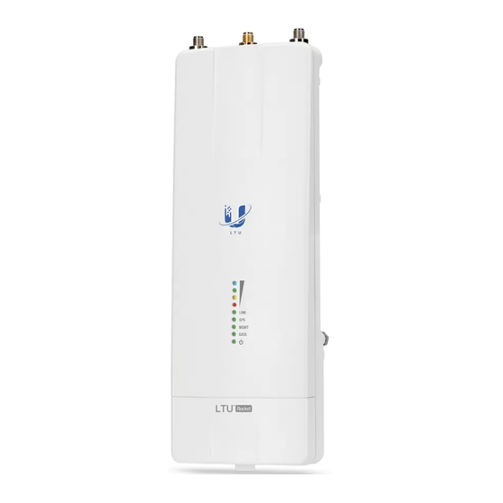
* Shown without antenna. Hardware Overview... - Page 4 LTU Antenna Connectors Used to attach RF antenna cables (not included). GPS Antenna Connector Used to attach the GPS Antenna.
- Page 5 Signal LEDs Each LED will light when the wireless signal strength is equal to or greater than the LED’s threshold value for the current channel width setting. The default threshold values for each channel width are shown below: Link LED RF Off Syncing Beaconing...
-
Page 6: Installation Overview
Gigabit PoE port for handling all user traffic and powering the device. Default IP address: 192.168.1.20 Installation Overview We recommend that you configure your LTU-Rocket radio before site installation. The following sections provide detailed installation instructions. Perform these instructions in the sequence given. - Page 7 Link Name, Duty Cycle, Channel Bandwidth, and Frequency. The PTMP stations will scan and find the LTU-Rocket and do not need any frequency set as long as they are set with the same Channel Bandwidth and Link Name.
- Page 8 3. Select your Country and Language. You must agree to the Terms of Use, EULA, and Privacy Policy to use the product. Click Continue. 4. Click the icon. 5. Configure the following settings: a. If needed, change the Channel Bandwidth, Frequency, Output Power (EIRP), Antenna Gain, and Max TX Modulation settings.
- Page 9 Change the IP Address, Netmask, and other settings to make them compatible with your network. c. Click Save Changes. Upgrade for IP67 Compliance To protect the LTU-Rocket from intrusion by water, dust, and insects, we recommend installing the IP67 Upgrade Kit (included):...
- Page 10 Note: Do not damage or remove the post on the Port Cover.
-
Page 11: Hardware Installation
Hardware Installation Installing the Ground Wire... - Page 12 The ground wire should be as short as possible and no longer than one meter in length. Mount to an airMAX Sector Antenna The LTU-Rocket is designed to mount directly onto the Ubiquiti antennas listed in “Antenna Compatibility”. The airMAX Sector antenna AM-5AC21-60 is shown in...
- Page 13 Mount the External GPS Antenna Locate a mounting point that has a clear view to the sky, and is above and as far away as possible from the LTU-Rocket. 1. ...
- Page 14 Connecting Power over Ethernet...
- Page 15 2. Note: If the IP67 Upgrade Kit is installed, first apply dielectric grease to the cable connector and port.
- Page 16 WARNING: The LTU-Rocket must receive a minimum of 15W. Ensure that the voltage range of the PoE source is within these limits: 4-pair operation: 18-54V 2-pair operation: 30-54V WARNING: Use only the included adapter, model POE-24V-5X-HD. Failure to do so can damage the unit and void the product warranty.
-
Page 17: Installer Compliance Responsibility
Antenna types not included in this list or having a gain greater than the maximum gain indicated for that type, are strictly prohibited for use with this device. Antenna Frequency Gain Sector 5 GHz 22 dBi Specifications LTU-Rocket... - Page 18 LTU-Rocket Dimensions 244 x 82 x 48 mm (9.61 x 3.23 x 1.89") Weight 0.468 kg (1.03 lb) RF Connectors (2) RP-SMA Weatherproof (CH0, CH1) (1) SMA Weatherproof (GPS) GPS Antenna External, Magnetic Base Power Supply 24VDC, 1A Gigabit, 4-Pair Passive PoE (Included)
-
Page 19: Safety Notices
Radio Max. Conducted TX Power 23 dBm Frequency Accuracy < 2 ppm Channel Bandwidth 10/20/30/40/50 MHz Selectable Programmable Uplink and Downlink Duty Cycles Operating Frequency (MHz) Worldwide 4800 - 6200 US/CA U-NII-1 5150 - 5250 U-NII-2A 5250 - 5350 U-NII-2C 5470 - 5725 U-NII-3 5725 - 5850... -
Page 20: Limited Warranty
death. c. Contact a qualified electrician or the manufacturer if there are questions about the installation prior to connecting the equipment. d. Protective earthing is provided by Listed AC adapter. Building installation shall provide appropriate short-circuit backup protection. e. Protective bonding must be installed in accordance with local national wiring rules and regulations. - Page 21 AVIS IMPORTANT Déclaration sur l’exposition aux rayonnements Cet équipement est conforme aux limites prévues pour l’exposition aux rayonnements dans un environnement non contrôlé. Lors de l’installation et de la mise en fonctionnement de l’équipement, assurez-vous qu’il y ait une distance minimale de 130 cm entre l’élément rayonnant et vous. Cet émetteur ne doit être installé...
-
Page 22: Declaration Of Conformity
WEEE Compliance Statement Declaration of Conformity Online Resources © 2020 Ubiquiti Inc. All rights reserved.
Need help?
Do you have a question about the LTU-Rocket and is the answer not in the manual?
Questions and answers