Advertisement
- 1 Introduction
- 2 Package Contents
- 3 Installation Requirements
- 4 Application Examples
- 5 LEDs
- 6 Hardware Installation
- 7 Connecting to Power over Ethernet
- 8 Mounting the PoE Adapter (Optional)
- 9 airOS Configuration
- 10 Installer Compliance Responsibility
- 11 Specifications
- 12 Safety Notices
- 13 Electrical Safety Information
- 14 Limited Warranty
- 15 Videos
- 16 Documents / Resources
Introduction
This Quick Start Guide is designed to guide you through installation and includes warranty terms.
Package Contents

* The Grid Reflector and mounting hardware are packaged separately. Products may be different from pictures and are subject to change without notice.
TERMS OF USE: Ubiquiti radio devices must be professionally installed. Shielded Ethernet cable and earth grounding must be used as conditions of product warranty. TOUGHCable designed for outdoor installations. It is the customer's responsibility to follow local country regulations, including operation within legal frequency channels, output power, and Dynamic Frequency Selection (DFS) requirements.
Installation Requirements
- 10 mm or 3/8" wrench
- Shielded Category 5 (or above) cabling should be used for all wired Ethernet connections and should be grounded through the AC ground of the PoE.
We recommend that you protect your networks from harmful outdoor environments and destructive ESD events with industrial‑grade, shielded Ethernet cable from Ubiquiti Networks. For more details, visit: www.ubnt.com/toughcable
Application Examples
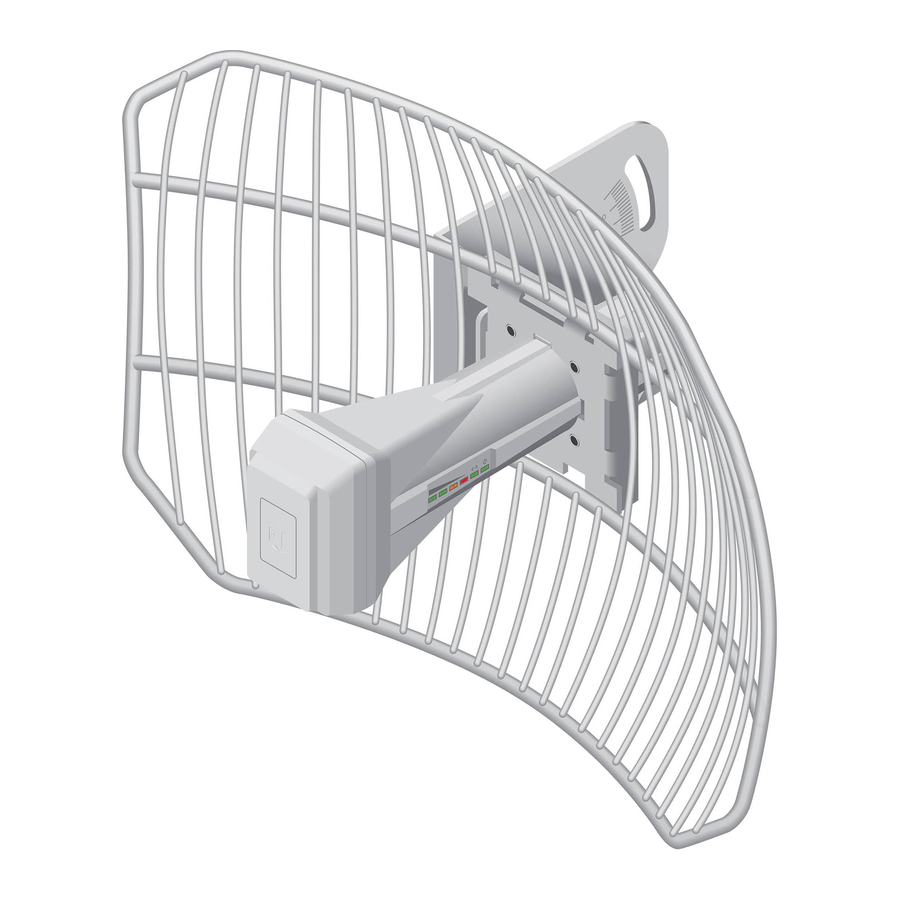
The airGrid mounted outdoors with the Grid Reflector installed provides directional outdoor coverage (gain reflector‑dependent).

The airGrid mounted outdoors without the Grid Reflector installed provides outdoor‑to‑indoor coverage using the 3 dBi Antenna Feed only.

LEDs

 | Signal In airOS, you can modify the wireless signal strength threshold values for each LED on the Advanced tab under Signal LED Thresholds. The default values are shown below: | |
 | LED will light green when the wireless signal strength is above ‑65 dBm. | |
| LED will light green when the wireless signal strength is above ‑73 dBm. | |
 | LED will light amber when the wireless signal strength is above ‑80 dBm. | |
 | LED will light red when the wireless signal strength is above ‑94 dBm. | |
 | Ethernet The Ethernet LED will light steady green when an active Ethernet connection is made and flash when there is activity. | |
 | Power The Power LED will light green when the device is connected to a power source. | |
Hardware Installation
Assemble the airGrid according to your chosen polarization.
- Attach the L-Bracket to the Grid Reflector by sliding the tabs into the slots.

![]()
The polarization of the airGrids must match on both ends of the wireless link (horizontal to horizontal, vertical to vertical). - On the front of the airGrid, ensure the polarization indicator, V or H, properly matches your desired polarization.

- Attach the Rear Housing:

- Ensure the four alignment holes on the Grid Reflector and L-Bracket are lined up.
- Orient the Rear Housing with the locking tab of the cable feed door facing up.
- Insert the alignments pins of the Rear Housing into the alignment holes, and push until the Rear Housing locks into place with a click.
- Lift the locking tab of the cable feed door and detach the door from the Rear Housing.

- Route an Ethernet cable through the Rear Housing. Connect the cable to the Ethernet port on the back of the Antenna Feed.

- Attach the Antenna Feed:

- Rotate the Antenna Feed to match the signal polarization.
- Insert the Antenna Feed into the Rear Housing, and push until it locks into place with a click.
- Lightly pull the Antenna Feed to ensure that the Release Button is fully engaged and locked into place.

![]() Note: If you need to remove the Antenna Feed, you must depress the Release Button first.
Note: If you need to remove the Antenna Feed, you must depress the Release Button first. - The Release Button indicates the Antenna Feed polarization. Confirm that the polarization indicator, V or H, on the Antenna Feed matches the indicator on the Grid Reflector.
![]()
The polarization indicators must match.

- Re-attach the cable feed door to the Rear Housing. Ensure the locking tab securely latches to the Rear Housing.

- Insert the U-Bolt into the Pole Clamp and L-Bracket. Secure each end of the U-Bolt with a Washer and Flange Nut.

![]() Note: The mounting assembly can accommodate a Ø 32 ‑ 56 mm (1.25 ‑ 2.2") pole.
Note: The mounting assembly can accommodate a Ø 32 ‑ 56 mm (1.25 ‑ 2.2") pole.


Connecting to Power over Ethernet

- Connect the Ethernet cable from the airGrid to the POE port of the PoE Adapter.
- Connect an Ethernet cable from your LAN to the LAN port of the PoE Adapter.
- Connect the Power Cord to the adapter, and then plug the Power Cord into a power outlet.
Mounting the PoE Adapter (Optional)
")
- Remove the PoE Mounting Bracket from the adapter, place the bracket at the desired location, and mark the two holes.
- Pre‑drill the holes if necessary, and secure the bracket using two fasteners (not included).
- Align the adapter's slots with the tabs of the PoE Mounting Bracket, and then slide the adapter down.
airOS® Configuration
Verify connectivity in the airOS Configuration Interface and select the airGrid antenna size.
- Make sure that your host system is connected via Ethernet to the airGrid.
- Configure the Ethernet adapter on your host system with a static IP address on the 192.168.1.x subnet.
- Launch your web browser and type https://192.168.1.20 in the address field. Press enter (PC) or return (Mac).

- The login screen will appear. Enter ubnt in the Username and Password fields. Select your Country and Language. You must agree to the Terms of Use to use the product. Click Login.
![]() Note: U.S. product versions are locked to the U.S. Country Code to ensure compliance with FCC regulations.
Note: U.S. product versions are locked to the U.S. Country Code to ensure compliance with FCC regulations.

- Select the airGrid antenna size:

Customize additional settings as needed to complete the installation.- Click the Wireless tab.
- From the Antenna drop-down list, select the appropriate option.
- Click Change to save.
- Click OK to confirm.


For additional details on the airOS Configuration Interface, refer to the User Guide available at: documentation.ubnt.com/airmax
Installer Compliance Responsibility
Devices must be professionally installed and it is the professional installer's responsibility to make sure the device is operated within local country regulatory requirements.

Since Ubiquiti Networks equipment can be paired with a variety of antennas and cables, the Antenna and Output Power fields are provided to the professional installer to assist in meeting regulatory requirements.
Specifications
| AG‑HP‑2G16 | |
| Dimensions | 370 x 270 x 270 mm (14.57 x 10.63 10.63") |
| Weight | 1478 g (52.13 oz) |
| Networking Interface | (1) 10/100 Ethernet Port |
| Enclosure | Outdoor UV Stabilized Plastic |
| Frequency | 2412 ‑ 2462 MHz |
| Gain | 16 dBi |
| Output Power | 28 dBm |
| Max. Power Consumption | 3W |
| Power Supply | 24V, 0.5A PoE Adapter (Included) |
| Power Method | Passive Power over Ethernet (Pairs 4, 5+; 7, 8 Return) |
| Max. VSWR | 1.5:1 |
| Wind Survivability | 200 km/h (125 mph) |
| Wind Loading | 34.7 N @ 200 km/h (7.8 lbf @ 125 mph) |
| ETSI Specification | EN 302 326 DN2 |
| Shock and Vibration | ETSI300‑019‑1.4 |
| Certifications | FCC, IC, CE |
| Operating Temperature | ‑30 to 75°C (‑22 to 167°F) |
| Operating Humidity | 5 to 95% Noncondensing |
Safety Notices
- Read, follow, and keep these instructions.
- Heed all warnings.
- Only use attachments/accessories specified by the manufacturer.
![]()
Do not use this product in location that can be submerged by water.
![]()
Avoid using this product during an electrical storm. There may be a remote risk of electric shock from lightning.


Electrical Safety Information
- Compliance is required with respect to voltage, frequency, and current requirements indicated on the manufacturer's label. Connection to a different power source than those specified may result in improper operation, damage to the equipment or pose a fire hazard if the limitations are not followed.
- There are no operator serviceable parts inside this equipment. Service should be provided only by a qualified service technician.
- This equipment is provided with a detachable power cord which has an integral safety ground wire intended for connection to a grounded safety outlet.
- Do not substitute the power cord with one that is not the provided approved type. Never use an adapter plug to connect to a 2‑wire outlet as this will defeat the continuity of the grounding wire.
- The equipment requires the use of the ground wire as a part of the safety certification, modification or misuse can provide a shock hazard that can result in serious injury or death.
- Contact a qualified electrician or the manufacturer if there are questions about the installation prior to connecting the equipment.
- Protective earthing is provided by Listed AC adapter. Building installation shall provide appropriate short‑circuit backup protection.
- Protective bonding must be installed in accordance with local national wiring rules and regulations.
Limited Warranty
UBIQUITI NETWORKS, Inc ("UBIQUITI NETWORKS") warrants that the product(s) furnished hereunder (the "Product(s)") shall be free from defects in material and workmanship for a period of one (1) year from the date of shipment by UBIQUITI NETWORKS under normal use and operation. UBIQUITI NETWORKS' sole and exclusive obligation and liability under the foregoing warranty shall be for UBIQUITI NETWORKS, at its discretion, to repair or replace any Product that fails to conform to the above warranty during the above warranty period. The expense of removal and reinstallation of any Product is not included in this warranty. The warranty period of any repaired or replaced Product shall not extend beyond its original term.
www.ubnt.com/support/warranty

VideosUbiquiti Airgrid M5 HP Point to Point Configuration Easy Step by Step (video)
Documents / Resources
References
Download manual
Here you can download full pdf version of manual, it may contain additional safety instructions, warranty information, FCC rules, etc.
Advertisement


Need help?
Do you have a question about the airGrid M2 HP and is the answer not in the manual?
Questions and answers