Table of Contents
Advertisement
Quick Links
Advertisement
Table of Contents

Related Manuals for Ubiquiti AF-5G30-S45


Summary of Contents for Ubiquiti AF-5G30-S45
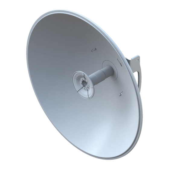
- Page 1 5 GHz, 30 dBi Slant 45 Antenna for airFiber ® Model: AF-5G30-S45...
-
Page 2: Package Contents
(Qty. 2) Guide (M10, Qty. 2) TERMS OF USE: Ubiquiti radio devices must be professionally installed. Shielded Ethernet cable and earth grounding must be used as conditions of product warranty. TOUGHCable ™ is designed for outdoor installations. It is the customer’s responsibility to follow local country regulations, including operation within legal frequency channels, output power, and Dynamic Frequency Selection (DFS) requirements. -
Page 3: Installation Requirements
Installation Requirements • airFiber AF‑5X radio (sold separately) • Phillips screwdriver • 13 mm wrench • Wrench or channel lock pliers with 63.5 mm (2.5") capacity • Mounting point: • At least 1 m below the highest point on the structure •... -
Page 4: Installation
Installation Important: Handle the Dish Reflector with care. Deformations in its shape may reduce the antenna's effectiveness. 1. Line up the alignment tabs of the Mounting Bracket with the alignment slots of the Dish Reflector. Insert the tabs and rotate the Mounting Bracket until they lock into place. Ensure that the antenna feed slot of the Note: Mounting Bracket lines up with the antenna feed slot... - Page 5 2. The Dish Reflector and Antenna Feed are keyed so the Antenna Feed can only be installed in a single orientation. Follow these steps: a. Remove the knob from the Antenna Feed. b. Line up the alignment pins of the Antenna Feed with the alignment holes of the Dish Reflector and Mounting Bracket.
- Page 6 3. To secure the Antenna Feed to the Dish Reflector: a. Replace the knob and tighten it by hand until the knob touches the surface of the Mounting Bracket. b. Use a wrench or channel lock pliers to tighten the knob an additional ¼...
- Page 7 4. Attach the airFiber radio to the Mounting Bracket. a. Align the mounting tabs on the back of the airFiber radio with the airFiber radio mount. b. Slide the airFiber radio down to lock it into place. 5. Attach the other end of the RF Cables to the RF connectors on the airFiber radio in this combination: +45°...
- Page 8 6. Attach the external GPS antenna (included with the airFiber radio) to the RF connector labeled GPS on the airFiber radio. Slide the jacket over the RF connector to protect it. Then place the magnetic external GPS antenna on the Dish Reflector (this is temporary;...
- Page 9 8. Attach two Hex Head Bolts, two Lock Washers, and two Flat Washers to the bottom of the Mounting Bracket. Ensure that there is a gap of 8 mm between each Flat Washer and the Mounting Bracket. Ensure that each Lock Washer is always Note: installed between the Hex Head Bolt and Flat Washer.
- Page 10 9. Attach the horizontal slot of the Support Arm to the Upper Pole Bracket using a Hex Head Bolt, Lock Washer, and Flat Washer. Ensure that the degree settings are the same Note: on both arms of the Upper Pole Bracket. Degree markings facing outward 10.
- Page 11 11. Each M8x150 Carriage Bolt includes a serrated flange nut. Remove these and use them in the next step. 12. Attach one Pole Clamp to each pole bracket. a. Insert two M8x150 Carriage Bolts into each pole bracket. b. Slide the hole of a Pole Clamp over one bolt of each pole bracket.
- Page 12 13. Attach the Stabilizer Brackets to the pole just beneath the area where the Antenna will be attached. Note: The pole‑bracket assembly can accommodate a Ø 38 ‑ 101 mm pole. a. Place one Stabilizer Bracket on each side of the pole. b.
- Page 13 14. Attach the pole‑bracket assembly to the pole: a. Slide the slot of each Pole Clamp over the corresponding M8x150 Carriage Bolt. b. Tighten the serrated flange nuts of the bolts to secure the pole‑bracket assembly to the pole. Proper slot orientation 25 N-m...
- Page 14 15. Lift the Dish Reflector and align the two lower Hex Head Bolts with the slots on the Lower Pole Bracket. Seat the bolts in the slots. 16. Attach each arm of the Upper Pole Bracket to the Mounting Bracket using a Hex Head Bolt, Lock Washer, and Flat Washer.
- Page 15 17. Before adjusting the tilt angle, ensure that the six Hex Head Bolts are loose enough to allow movement. If you cannot spin the washers freely by IMPORTANT: hand, then loosen the Hex Head Bolts until you can. 18. To adjust the tilt angle, turn the screw head of the Elevation Rod until the desired tilt is reached.
-
Page 16: Mounting The External Gps Antenna
Mounting the External GPS Antenna Locate a mounting point that has a clear view to the sky, and is above and as far away as possible from the AF‑5G30‑S45. Note: All GPS items are included with the airFiber radio. 1. Attach the GPS antenna mount to the pole using the metal strap, or attach it to a wall using the appropriate fasteners (not included). -
Page 17: Specifications
Specifications AF‑5G30‑S45 Dimensions 650 x 650 x386 mm (25.6 x 25.6 x 15.2") Weight 7.4 kg (16.31 lb) (Mount Included) Frequency 5.1 ‑ 5.9 GHz Gain 30 dBi Max. VSWR 1.6:1 Wind Survivability 200 km/h (125 mph) Wind Loading 790 N @ 200 km/h (178 lbf @ 125 mph) Polarization Dual Linear F/B Ratio... -
Page 18: Limited Warranty
(VI) has no original Ubiquiti MAC label, or is missing any other original Ubiquiti label(s); or (VII) has not been received by Ubiquiti within 30 days of issuance of the RMA. -
Page 19: Limitation Of Liability
SUBJECT TO LIMITATIONS, INTERRUPTIONS, DELAYS, CANCELLATIONS AND OTHER PROBLEMS INHERENT IN THE USE OF COMMUNICATIONS FACILITIES. UBIQUITI NETWORKS, ITS AFFILIATES AND ITS AND THEIR THIRD PARTY PROVIDERS ARE NOT RESPONSIBLE FOR ANY INTERRUPTIONS, DELAYS, CANCELLATIONS, DELIVERY FAILURES, DATA LOSS, CONTENT CORRUPTION, PACKET LOSS, OR OTHER DAMAGE RESULTING FROM ANY OF THE FOREGOING. - Page 20 Note Some countries, states and provinces do not allow exclusions of implied warranties or conditions, so the above exclusion may not apply to you. You may have other rights that vary from country to country, state to state, or province to province. Some countries, states and provinces do not allow the exclusion or limitation of liability for incidental or consequential damages, so the above limitation may not apply to you.
- Page 21 RoHS/WEEE Compliance Statement English European Directive 2002/96/EC requires that the equipment bearing this symbol on the product and/or its packaging must not be disposed of with unsorted municipal waste. The symbol indicates that this product should be disposed of separately from regular household waste streams.
- Page 22 Español La Directiva 2002/96/CE de la UE exige que los equipos que lleven este símbolo en el propio aparato y/o en su embalaje no deben eliminarse junto con otros residuos urbanos no seleccionados. El símbolo indica que el producto en cuestión debe separarse de los residuos domésticos convencionales con vistas a su eliminación.
-
Page 23: Declaration Of Conformity
[German] Anforderungen und den anderen relevanten Vorschriften der Richtlinie 1999/5/EG befindet. Ελληνική Δια του παρόντος, UBIQUITI NETWORKS, δηλώνει ότι αυτή η συσκευή UBIQUITI NETWORKS, είναι σε συμμόρφωση με τις [Greek] βασικές απαιτήσεις και τις λοιπές σχετικές διατάξεις της οδηγίας 1995/5/ΕΚ. -
Page 24: Online Resources
. u b n t . c o m ©2014‑2015 Ubiquiti Networks, Inc. All rights reserved. All rights reserved. Ubiquiti, Ubiquiti Networks, the Ubiquiti U logo, the Ubiquiti beam logo, airFiber, and TOUGHCable are trademarks or registered trademarks of Ubiquiti Networks, Inc. in the United States and in other countries.
Need help?
Do you have a question about the AF-5G30-S45 and is the answer not in the manual?
Questions and answers