Table of Contents
Advertisement
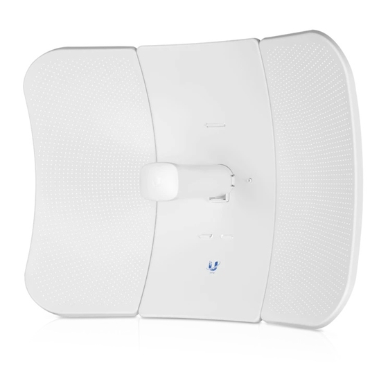
Package Contents
Antenna Feed
Mounting Bracket
M4 SEM Screws (Qty. 8)
Gigabit PoE (24V, 0.5A) with
Mounting Bracket
Installation Requirements
LTU PtMP AP, such as model LTU-Rocket
Phillips screwdriver
13 mm wrench
8 mm socket wrench or screwdriver
Surge protection should be used for all outdoor installations. We recommend that
you use two Ethernet Surge Protectors, model ETH-SP-G2, one near the device and
the other at the entry point to the building. The ETH-SP-G2 will absorb power surges
and safely discharge them into the ground.
Note: For guidelines about grounding and lightning protection, follow your
local electrical regulatory codes.
LTU-LR Quick Start Guide
Center Reflector Panel
Rear Housing
M8 SEM Screws (Qty. 4)
Power Cord
Side Reflector Panels (Qty. 2)
Pivot Panels (Qty. 2)
Metal Straps (Qty. 3)
Advertisement
Table of Contents

Related Manuals for Ubiquiti LTU-LR


Summary of Contents for Ubiquiti LTU-LR
- Page 1 LTU-LR Quick Start Guide Package Contents Antenna Feed Center Reflector Panel Side Reflector Panels (Qty. 2) Mounting Bracket Rear Housing Pivot Panels (Qty. 2) M4 SEM Screws (Qty. 8) M8 SEM Screws (Qty. 4) Metal Straps (Qty. 3) Gigabit PoE (24V, 0.5A) with Power Cord Mounting Bracket Installation Requirements LTU PtMP AP, such as model LTU-Rocket Phillips screwdriver 13 mm wrench 8 mm socket wrench or screwdriver Surge protection should be used for all outdoor installations. We recommend that you use two Ethernet Surge Protectors, model ETH-SP-G2, one near the device and the other at the entry point to the building. The ETH-SP-G2 will absorb power surges and safely discharge them into the ground. Note: For guidelines about grounding and lightning protection, follow your local electrical regulatory codes.
-
Page 2: Hardware Overview
Outdoor, shielded Category 6 (or above) cabling and shielded RJ45 connectors are required for all wired Ethernet connections. Hardware Overview LAN LED The LED will light steady blue when an active Ethernet connection is made to the Ethernet port and flash when there is activity. Power LED The LED will light blue when the device is connected to a power source. Reset Button To reset to factory defaults, press and hold the Reset button for more than 10 seconds while the device is powered on. PoE In [24V] Port This 10/100/1000 Ethernet port is used to connect the power and should be... -
Page 3: Hardware Installation
connected to the LAN. Default IP address: 192.168.1.20 Hardware Installation... - Page 7 10.
- Page 8 Pole Mounting...
-
Page 10: Connecting Power
Connecting Power WARNING: The switch port must comply with the power specifications listed in the “Specifications”. -
Page 11: Accessing The Configuration Interface
Optional Accessing the Configuration Interface 1. Make sure that your host system is connected via Ethernet to the device. 2. Configure the Ethernet adapter on your host system with a static IP address on the 192.168.1.x subnet. 3. Launch your web browser and type https://192.168.1.20 in the address field. Press enter (PC) or return (Mac). 4. Select your Country and Language. You must agree to the Terms of Use, EULA, and Privacy Policy to use the product. Click Continue. - Page 12 The LTU Configuration Interface will appear, allowing you to customize your settings as needed. To have your AP configure your device, proceed to “Find My AP”. UNMS Management You can manage your device using UNMS, which lets you configure, monitor, upgrade, and back up your devices using a single application. Get started at www.unms.com Find My AP 1. Click the icon. 2. In the Wireless Settings section, change the channel bandwidth (default: 20 MHz) as needed. Note: If the AP’s channel bandwidth is set to 50 MHz and your device is set to 20 MHz, then your device will not see that AP and you should change the channel bandwidth on your device. 3. Click Find AP. 4. The device will scan for nearby APs. Click Select for the appropriate AP. To run the search again, click Scan.
-
Page 13: Installer Compliance Responsibility
5. Follow the on-screen instructions. Installer Compliance Responsibility Devices must be professionally installed and it is the professional installer's responsibility to make sure the device is operated within local country regulatory requirements. Antenna Select your antenna from the list. If Calculate EIRP Limit is enabled, transmit output power is automatically adjusted to comply with the regulations of the applicable country. For a Custom antenna, Antenna Gain is entered manually. Note the requirements and antenna types listed below. Cable Loss (When applicable) Enter the cable loss in dB. Output power is adjusted to compensate for loss between the radio and the antenna. Certified Antenna Types This radio transmitter FCC ID: SWX-LTULRR / IC: LTULRR has been approved by FCC / ISED Canada to operate with the antenna types listed below with the maximum permissible gain for each antenna type indicated. Antenna types not included in this list or having a gain greater than the maximum gain indicated for that type, are strictly prohibited for use with this device. Antenna Frequency Gain Grid 5 GHz 26 dBi Feed Only (Omni) 5 GHz 3 dBi Specifications LTU-LR Dimensions 512.5 x 385.75 x 258.3 mm (20.18 x 15.19 x 10.17") -
Page 14: Safety Notices
Weight 1.360 kg (2.998 lb) With Mount 1.735 kg (3.825 lb) Networking Interface (1) 10/100/1000 Ethernet Port Enclosure Outdoor UV Stabilized Plastic Max. Power Consumption 8.5W Power Supply 24V, 0.5A Gigabit PoE Adapter Power Method 24V Passive PoE (Pairs 4, 5+; 7, 8-) Supported Voltage Range 22 - 26V Gain 26 dBi Max. Conducted TX Power 22 dBm Mounting Pole-Mount (Kit Included) Wind Loading 550 N @ 200 km/h (123.6 lbf @ 125 mph) Wind Survivability 200 km/h (125 mph) ESD/EMP Protection ± 24 kV Contact / Air Operating Temperature -40 to 60° C (-40 to 140° F) Operating Humidity 5 to 95% Noncondensing Certifications CE, FCC, IC Operating Frequency (MHz) Worldwide 4800 - 6200* US/CA U-NII-1 5150 - 5250 U-NII-2A... -
Page 15: Limited Warranty
c. Contact a qualified electrician or the manufacturer if there are questions about the installation prior to connecting the equipment. d. Protective earthing is provided by Listed AC adapter. Building installation shall provide appropriate short-circuit backup protection. e. Protective bonding must be installed in accordance with local national wiring rules and regulations. Limited Warranty ui.com/support/warranty The limited warranty requires the use of arbitration to resolve disputes on an individual basis, and, where applicable, specify arbitration instead of jury trials or class actions. Compliance Changes or modifications not expressly approved by the party responsible for compliance could void the user’s authority to operate the equipment. This device complies with Part 15 of the FCC Rules. Operation is subject to the following two conditions. 1. This device may not cause harmful interference, and 2. This device must accept any interference received, including interference that may cause undesired operation. This equipment has been tested and found to comply with the limits for a Class A digital device, pursuant to part 15 of the FCC Rules. These limits are designed to provide reasonable protection against harmful interference when the equipment is operated in a commercial environment. This equipment generates, uses, and can radiate radio frequency energy and, if not installed and used in accordance with the instruction manual, may cause harmful interference to radio communications. Operations of this equipment in a residential area is likely to cause harmful interference in which case the user will be required to correct the interference at his own expense. This radio transmitter has been approved by FCC. ISED Canada CAN ICES-3(A)/NMB-3(A) This device complies with ISED Canada licence-exempt RSS standard(s). Operation is subject to the following two conditions: 1. This device may not cause interference, and 2. This device must accept any interference, including interference that may cause undesired operation of the device. This radio transmitter has been approved by ISED Canada. -
Page 16: Declaration Of Conformity
AVIS IMPORTANT Déclaration sur l’exposition aux rayonnements Cet équipement est conforme aux limites prévues pour l’exposition aux rayonnements dans un environnement non contrôlé. Lors de l’installation et de la mise en fonctionnement de l’équipement, assurez-vous qu’il y ait une distance minimale de 103 cm entre l’élément rayonnant et vous. Cet émetteur ne doit être installé à proximité d’aucune autre antenne ni d’aucun autre émetteur, et ne doit être utilisé conjointement à aucun autre de ces appareils. Australia and New Zealand Warning: This equipment is compliant with Class A of CISPR 32. In a residential environment this equipment may cause radio interference. Brazil Nota: Este equipamento não tem direito à proteção contra interferência prejudicial e não pode causar interferência em sistemas devidamente autorizados. CE Marking CE marking on this product represents the product is in compliance with all directives that are applicable to it. Country List BFWA (Broadband Fixed Wireless Access) members noted in blue Note: This device meets Max. TX power limit per ETSI regulations. The following apply to products that operate in the 5 GHz frequency range: Note: This device is restricted to indoor use only when operating in the 5150 - 5350 MHz frequency range within all member states. Note: All countries listed may operate at 30 dBm. BFWA member states may operate at 36 dBm. Note: Operation in the 5.8 GHz frequency band is prohibited in BFWA member states. Other countries listed may use the 5.8 GHz frequency band. WEEE Compliance Statement Declaration of Conformity Online Resources... - Page 17 © 2020 Ubiquiti Inc. All rights reserved.
Need help?
Do you have a question about the LTU-LR and is the answer not in the manual?
Questions and answers