Table of Contents
Advertisement
Quick Links
Important Notice
NXP provides the enclosed product(s) under the following conditions:
This evaluation kit is intended for use of ENGINEERING DEVELOPMENT OR EVALUATION PURPOSES ONLY. It is provided as a
sample IC pre-soldered to a printed circuit board to make it easier to access inputs, outputs, and supply terminals. This evaluation board
may be used with any development system or other source of I/O signals by simply connecting it to the host MCU or computer board via
off-the-shelf cables. This evaluation board is not a Reference Design and is not intended to represent a final design recommendation for
any particular application. Final device in an application will be heavily dependent on proper printed circuit board layout and heat sinking
design as well as attention to supply filtering, transient suppression, and I/O signal quality.
The goods provided may not be complete in terms of required design, marketing, and or manufacturing related protective considerations,
including product safety measures typically found in the end product incorporating the goods. Due to the open construction of the product,
it is the user's responsibility to take any and all appropriate precautions with regard to electrostatic discharge. In order to minimize risks
associated with the customers applications, adequate design and operating safeguards must be provided by the customer to minimize
inherent or procedural hazards. For any safety concerns, contact NXP sales and technical support services.
Should this evaluation kit not meet the specifications indicated in the kit, it may be returned within 30 days from the date of delivery and will
be replaced by a new kit.
NXP reserves the right to make changes without further notice to any products herein. NXP makes no warranty, representation or
guarantee regarding the suitability of its products for any particular purpose, nor does NXP assume any liability arising out of the
application or use of any product or circuit, and specifically disclaims any and all liability, including without limitation consequential or
incidental damages. "Typical" parameters can and do vary in different applications and actual performance may vary over time. All
operating parameters, including "Typical", must be validated for each customer application by customer's technical experts.
NXP does not convey any license under its patent rights nor the rights of others. NXP products are not designed, intended, or authorized
for use as components in systems intended for surgical implant into the body, or other applications intended to support or sustain life, or
for any other application in which the failure of the NXP product could create a situation where personal injury or death may occur.
Should the Buyer purchase or use NXP products for any such unintended or unauthorized application, the Buyer shall indemnify and hold
NXP and its officers, employees, subsidiaries, affiliates, and distributors harmless against all claims, costs, damages, and expenses, and
reasonable attorney fees arising out of, directly or indirectly, any claim of personal injury or death associated with such unintended or
unauthorized use, even if such claim alleges NXP was negligent regarding the design or manufacture of the part.
UM11108
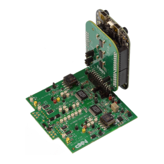
FRDM-GD3100EVM half-bridge evaluation board
Rev. 5 — 10 February 2020
User manual
Advertisement
Table of Contents

Subscribe to Our Youtube Channel
Related Manuals for NXP Semiconductors SAFE ASSURE FRDM-GD3100EVM


Summary of Contents for NXP Semiconductors SAFE ASSURE FRDM-GD3100EVM
- Page 1 UM11108 FRDM-GD3100EVM half-bridge evaluation board Rev. 5 — 10 February 2020 User manual Important Notice NXP provides the enclosed product(s) under the following conditions: This evaluation kit is intended for use of ENGINEERING DEVELOPMENT OR EVALUATION PURPOSES ONLY. It is provided as a sample IC pre-soldered to a printed circuit board to make it easier to access inputs, outputs, and supply terminals.
-
Page 2: Finding Kit Resources And Information On
FRDM-GD3100EVM half-bridge evaluation board Finding kit resources and information on the NXP web site NXP Semiconductors provides online resources for this evaluation board and its supported device(s) on http:/www.nxp.com. The information page for FRDM-GD3100EVM Rev C half-bridge evaluation board is at http://www.nxp.com/FRDM-GD3100EVM. -
Page 3: Windows Pc Workstation
UM11108 NXP Semiconductors FRDM-GD3100EVM half-bridge evaluation board • Rogowski coil, PEM Model CWT Mini HF60R or CTW Mini HF30 (smaller diameter) • Two isolated high voltage probes (CAL Test Electric CT2593-1, LeCroy AP030) • Four low voltage probes • Two digital voltmeters 2.3 Windows PC workstation... -
Page 4: Device Features
UM11108 NXP Semiconductors FRDM-GD3100EVM half-bridge evaluation board 3.3 Device features Table 1. Device features Device Description Features GD3100 The GD3100 is an advanced • Compliant with ASIL C/D ISO 26262 functional single channel gate driver for safety requirements IGBTs. • SPI interface for safety monitoring, programmability and flexibility •... -
Page 5: Low-Voltage Logic And Controls Connector
UM11108 NXP Semiconductors FRDM-GD3100EVM half-bridge evaluation board 3.4.1 Low-voltage logic and controls connector Low-voltage domain is 12 V VSUP/VPWR domain that interfaces with the MCU and GD3100 control registers through the 24-pin connector interface. Low-side driver and high-side driver domains are driver control interfaces to IGBT single phase connections and test points. -
Page 6: Test Point Definitions
UM11108 NXP Semiconductors FRDM-GD3100EVM half-bridge evaluation board Name Function n.c. No connection MOSIH Master out slave in (high-side) n.c. No connection CSBH Chip select bar (high-side) LED_PWR 3.3 V supply for INTB LEDs (high-side and low-side) AOUTH Duty cycle encoded signal (high-side) - Page 7 UM11108 NXP Semiconductors FRDM-GD3100EVM half-bridge evaluation board Figure 3. Key test point locations Table 3. Driver board test point definitions Test point Reference Definition designator Low voltage (LV) domain TP17, TP18, TP19, Grounding points for low-voltage domain TP20 VPWR DC voltage source connection point for VSUP power input of GD3100 devices and flyback power supplies.
- Page 8 UM11108 NXP Semiconductors FRDM-GD3100EVM half-bridge evaluation board Test point Reference Definition designator AMUXINL TP31 Test point for analog MUX input for low-side driver. Can be used for monitoring DC bus voltage. CLAMPL TP29 VCE sense test point connected to low-side driver clamp pin and...
-
Page 9: Power Related Jumpers Configuration
UM11108 NXP Semiconductors FRDM-GD3100EVM half-bridge evaluation board 3.4.3 Power related jumpers configuration Figure 4. Power supply and jumpers configuration Table 4. Power related jumper definitions Jumper Reference Position Function designator VCCH Open VCC regulator (VCCREG) active, gate driver (GH) uses VCCREG (default) -
Page 10: Configuring Power Delivery To Gd3100
UM11108 NXP Semiconductors FRDM-GD3100EVM half-bridge evaluation board Jumper Reference Position Function designator VDDL Open VDD-VSUP are separate. Device powered from VSUP, VDD uses internal regulator (default) Closed VDD-VSUP connected. VDD internal regulator bypassed. Device powered by external 5.0 V. VSUPL... -
Page 11: Signal Related Jumpers And Configuration
UM11108 NXP Semiconductors FRDM-GD3100EVM half-bridge evaluation board • Short VCCH (J4) jumper • Short VCCL (J7) jumper • Tune VCC-GNDx output voltage (high and low sides) with feedback resistor (R3) 3.4.4 Signal related jumpers and configuration Figure 5. Signal related jumper locations Table 5. Signal related jumper configurations... -
Page 12: Spi Configuration Options
UM11108 NXP Semiconductors FRDM-GD3100EVM half-bridge evaluation board Jumper Reference Position Function designator MISO MISOL is passed directly to MCU. Use for normal SPI mode. (default) MISOL is passed to MOSIH. Use for daisy-chain SPI mode. Open Not allowed. MISOL is not routed anywhere for valid communication. -
Page 13: Configuring Dead Time Application In Hardware
UM11108 NXP Semiconductors FRDM-GD3100EVM half-bridge evaluation board 3.4.4.2 Configuring dead time application in hardware To enable dead time and cross-conduction protection, PWMALT receives complimentary signals (default): • Set PWMALTH_SEL (J22) to 1-2 • Set PWMALTL_SEL (J21) to 1-2 To bypass dead time insertion (set PWMALT = 0) for specialized testing: •... -
Page 14: Led Interrupt Indicators
UM11108 NXP Semiconductors FRDM-GD3100EVM half-bridge evaluation board • RAMC - series resistor between IGBT gate and AMC input pin of the GD3100 high- side/low-side driver for gate sensing and Active Miller clamping. Figure 7. Gate drive resistors 3.4.7 LED interrupt indicators Interrupt LEDs are provided to visually alert the user of a reported fault. -
Page 15: Kinetis Kl25Z Freedom Board
UM11108 NXP Semiconductors FRDM-GD3100EVM half-bridge evaluation board Table 6. Interrupt LED definitions Reference Description designator Low-side INTB Connected to the INTB output pin (active low) of low-side GD3100 • LED is ON: indicates reported fault, check system • LED is OFF: indicates no reported fault... - Page 16 UM11108 NXP Semiconductors FRDM-GD3100EVM half-bridge evaluation board Figure 10. Logic translator board Table 7. Translator board jumper functionality Jumper Reference Position Function designator VCCSEL J233 5.0 V regulator from KL25Z powers all translator VCC, 5.0 V signals to/from the driver board (default) •...
-
Page 17: Configuring The Translator For Kl25Z-Controlled Pwm
UM11108 NXP Semiconductors FRDM-GD3100EVM half-bridge evaluation board The translator board in FRDM-GD3100EVM Rev C supports different configurations for various application tests. The translator supports PWM from either the KL25Z (see Section 3.6.1 "Configuring the translator for KL25Z-controlled PWM") or from external source (see Section 3.6.2 "Configuring the translator for external PWM... -
Page 18: Configuring The Hardware
UM11108 NXP Semiconductors FRDM-GD3100EVM half-bridge evaluation board Configuring the hardware 4.1 System setup FRDM-GD3100EVM Rev C is connected to any phase of an Fuji Electric M653 or M661 IGBT module with SBE DC Link capacitor as shown in Figure 11. Double pulse and short-circuit testing can be conducted utilizing Windows based PC with SPIGEN software. -
Page 19: Quick Start
UM11108 NXP Semiconductors FRDM-GD3100EVM half-bridge evaluation board 4.2 Quick start 4.2.1 Scope and purpose This section provides comprehensive quick start notes for the FRDM-GD3100EVM Rev C half-bridge evaluation kit. Within a few minutes the user can install SPIGEN application on a PC, power up the half-bridge evaluation kit, start SPI communication, and pass PWM signals to evaluate working operation. -
Page 20: Installation And Use Of Software Tools
UM11108 NXP Semiconductors FRDM-GD3100EVM half-bridge evaluation board a. To receive PWM as provided by the KL25Z, see Section 3.6.1 "Configuring the translator for KL25Z-controlled PWM". Use SPIGen to control, see Section 5.3.4 "Pulse test". b. b. To set up for external PWM control, see Section 3.6.2 "Configuring the translator... -
Page 21: Configuring The Frdm-Kl25Z Microcode
UM11108 NXP Semiconductors FRDM-GD3100EVM half-bridge evaluation board Installing the device drivers overwrites any previous SPIGen installation and replaces it with a current version containing the GD3100 drivers. However, configuration files (.spi) from the previous version remain intact. 5.2 Configuring the FRDM-KL25Z microcode By default, the FRDM-KL25Z with this kit is preprogrammed with the current and most up-to-date firmware available for the kit. -
Page 22: Using The Spigen Graphical User Interface
UM11108 NXP Semiconductors FRDM-GD3100EVM half-bridge evaluation board 5.3 Using the SPIGEN graphical user interface The SPIGen graphical user interface is available from NXP.com as an evaluation tool demonstrating GD3100-specific functionality, configuration, and fault reporting. SPIGen also includes basic capacity for the FRDM-GD3100EVM Rev C to control an IGBT, enabling double-pulse or short-circuit testing. -
Page 23: Configuration Register
UM11108 NXP Semiconductors FRDM-GD3100EVM half-bridge evaluation board Figure 14. Mode registers and GPIO controls view 5.3.2 Configuration register See GD3100 data sheet for configuration SPI register descriptions. When attempting to change configuration parameters, ensure the CONFIG_EN bit in the MODE2 register is set to 1. READ operations send identical back-to-back commands so the response is obtained upon a single click of the Read button. -
Page 24: Status And Mask Register
UM11108 NXP Semiconductors FRDM-GD3100EVM half-bridge evaluation board 5.3.3 Status and mask register See GD3100 data sheet for status and mask SPI register descriptions. INTB indicators mirror the status of the INTB pin on both high-side and low-side GD3100 simultaneously, but only one (either high-side or low-side) can be read at a time over SPI (selected by “SPI 0”... -
Page 25: Daisy Chain
UM11108 NXP Semiconductors FRDM-GD3100EVM half-bridge evaluation board Figure 17. Pulse test view 5.3.5 Daisy chain When FRDM-GD3100EVM Rev C is configured for daisy-chain (see Section 3.4.4.1 "SPI configuration options"), both GD3100 devices can be addressed in the same SPI frame. In daisy-chain configuration, both devices will be addressed by “SPI 0”. Neither device will be addressed if “SPI 1”... -
Page 26: Batch Command
UM11108 NXP Semiconductors FRDM-GD3100EVM half-bridge evaluation board Figure 19. Single command view 5.3.7 Batch command The Batch commands view allows creation of scripts containing commands defined by the Single command page. Batches can be named, saved, and recalled. This is useful for quickly initializing the device after powering up. -
Page 27: Troubleshooting
UM11108 NXP Semiconductors FRDM-GD3100EVM half-bridge evaluation board 5.4 Troubleshooting Some common issues and troubleshooting procedures are detailed below. This is not an exhaustive list by any means, and additional debug may be needed: Problem Evaluation Explanation Corrective action(s) No PWM output (no fault reported) - Page 28 UM11108 NXP Semiconductors FRDM-GD3100EVM half-bridge evaluation board Problem Evaluation Explanation Corrective action(s) WDOG_FLT reported on startup Check VSUP and VCC are powered On initialization, watchdog fault is Check VSUP and VCC both have reported when one die is powered up power applied.
-
Page 29: Materials
UM11108 NXP Semiconductors FRDM-GD3100EVM half-bridge evaluation board Schematics, board layout and bill of materials The board schematics, board layout and bill of materials are available at http:// www.nxp.com/FRDM-GD3100EVM. References Tool summary page for FRDM-GD3100EVM Rev C http://www.nxp.com/FRDM-GD3100EVM Product summary page for MC33GD3100 device http://www.nxp.com/GD3100... -
Page 30: Legal Information
Customer is responsible for doing all necessary testing for the customer’s applications and products using NXP Semiconductors products in order to avoid a Draft — The document is a draft version only. The content is still under... - Page 31 UM11108 NXP Semiconductors FRDM-GD3100EVM half-bridge evaluation board Tables Tab. 1. Device features ..........4 Tab. 5. Signal related jumper configurations ....11 Tab. 2. Low-voltage (LV) domain 24-pin connector Tab. 6. Interrupt LED definitions ........15 definitions ............5 Tab. 7.
-
Page 32: Table Of Contents
UM11108 NXP Semiconductors FRDM-GD3100EVM half-bridge evaluation board Contents Finding kit resources and information on 5.3.6 Single command ..........25 the NXP web site ..........2 5.3.7 Batch command ..........26 Collaborate in the NXP Community ....2 Troubleshooting ..........27 Getting started ............ 2 Schematics, board layout and bill of Kit contents ............2... - Page 33 Mouser Electronics Authorized Distributor Click to View Pricing, Inventory, Delivery & Lifecycle Information: FRDM-GD3100EVM...
Need help?
Do you have a question about the SAFE ASSURE FRDM-GD3100EVM and is the answer not in the manual?
Questions and answers