
Subscribe to Our Youtube Channel
Related Manuals for NXP Semiconductors SAFE ASSURE FRDMGD3100HB8EVM


Summary of Contents for NXP Semiconductors SAFE ASSURE FRDMGD3100HB8EVM
-
Page 1: Frdmgd3100Hb8Evm
UM11440 FRDMGD3100HB8EVM half-bridge evaluation board Rev. 1 — 4 August 2020 User guide FRDMGD3100HB8EVM... - Page 2 UM11440 NXP Semiconductors FRDMGD3100HB8EVM half-bridge evaluation board Important Notice NXP provides the enclosed product(s) under the following conditions: This evaluation kit is intended for use of ENGINEERING DEVELOPMENT OR EVALUATION PURPOSES ONLY. It is provided as a sample IC pre-soldered to a printed circuit board to make it easier to access inputs, outputs, and supply terminals. This evaluation board may be used with any development system or other source of I/O signals by simply connecting it to the host MCU or computer board via off-the-shelf cables.
-
Page 3: Getting Started
UM11440 NXP Semiconductors FRDMGD3100HB8EVM half-bridge evaluation board Getting started NXP analog product development boards provide a platform for evaluating a broad range of NXP analog, mixed-signal and power solution products. NXP analog product development boards incorporate monolithic integrated circuits and system-in-package devices that use proven high-volume technology. -
Page 4: Required Equipment
UM11440 NXP Semiconductors FRDMGD3100HB8EVM half-bridge evaluation board 2.2 Required equipment The kit requires the following equipment: • Compatible SiC module • DC link capacitor compatible with the SiC module • 30 µH to 50 µH, high current air core inductor for double pulse testing •... -
Page 5: Device Features
UM11440 NXP Semiconductors FRDMGD3100HB8EVM half-bridge evaluation board 3.3 Device features Table 1. Device features Device Description Features MC33GD3100 The MC33GD3100 is • Compatible with current sense and temp sense an advanced single IGBTs channel gate driver for • DESAT detection capability for detecting V IGBTs. -
Page 6: Low-Voltage Logic And Control Connector
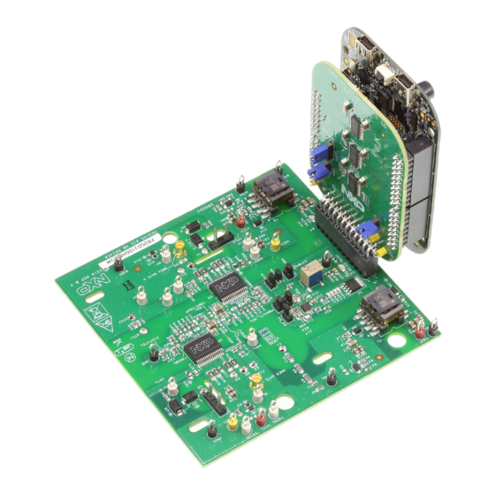
UM11440 NXP Semiconductors FRDMGD3100HB8EVM half-bridge evaluation board Figure 1. Connecting FRDM-KL25Z, FRDMGD3100HB8EVM and GD3100 translator board 3.4.1 Low-voltage logic and control connector The low-voltage domain is 12 V VSUP domain that interfaces with the MCU and MC33GD3100 control registers through the 24-pin connector interface. - Page 7 UM11440 NXP Semiconductors FRDMGD3100HB8EVM half-bridge evaluation board Figure 2. FRDMGD3100HB8EVM board voltage and interface domains Table 2. Low-voltage domain 24-pin connector definitions Name Function AOUTL analog output duty cycle encoded signal (low side) for reading temperature via TSENSEA or voltage via AMUXIN n.c.
-
Page 8: Test Point Definitions
UM11440 NXP Semiconductors FRDMGD3100HB8EVM half-bridge evaluation board Name Function CSBH chip select bar (high side) LED_PWR USB 3.3 V power for INTB LEDs (high side and low side) AOUTH duty cycle encoded signal (high side) PWMH PWM input (high side) - Page 9 UM11440 NXP Semiconductors FRDMGD3100HB8EVM half-bridge evaluation board Table 3. Test point definitions–low voltage/low-side driver domains Name Test Point Definition Low-voltage domain GND (1) Grounding points for low-voltage domain INTBH TP20 Test point for interrupt bar high-side INTBL TP11 Test point for interrupt bar low-side...
- Page 10 UM11440 NXP Semiconductors FRDMGD3100HB8EVM half-bridge evaluation board Figure 4. Test point definitions - high-side driver domain Table 4. Test point definition - high-side driver Name Test point Definition AMXH TP23 High-side driver test point for analog MUX input COLH J101 Collector test point/connection high-side...
-
Page 11: Power Supply And Jumper Configuration
UM11440 NXP Semiconductors FRDMGD3100HB8EVM half-bridge evaluation board 3.4.3 Power supply and jumper configuration Figure 5. Power supply and jumper configuration Table 5. Jumper definitions Jumper Position Function Dead time fault protection enabled (high side) PWMALTL_SEL (J4) Dead time fault protection disabled (use for short-circuit testing) 1–2... -
Page 12: Bottom View
UM11440 NXP Semiconductors FRDMGD3100HB8EVM half-bridge evaluation board Table 6. Power Supply Definition Component Definition Flyback MOSFET AEC Q101-compliant logic level N-channel MOSFET (Q1) Potentiometer (R32) Adjusts resistor R3 for VCCH/VCCL and VEEH/VEEL Tune VCC-GNDISO FOR +17V 3.4.4 Bottom view Figure 6. FRDMGD3100HB8EVM bottom view 3.4.5 Gate drive resistors... -
Page 13: Led Interrupt Indicators
UM11440 NXP Semiconductors FRDMGD3100HB8EVM half-bridge evaluation board Figure 7. Gate drive resistors 3.4.6 LED interrupt indicators Figure 8. LED interrupt indicators UM11440 All information provided in this document is subject to legal disclaimers. © NXP B.V. 2020. All rights reserved. User guide Rev. -
Page 14: Kinetis Kl25Z Freedom Board
UM11440 NXP Semiconductors FRDMGD3100HB8EVM half-bridge evaluation board Table 7. LED interrupt indicators Description Low-side INTB connected to the INTB output pin of low-side driver indicating reported fault status when on (active LOW) High-side INTB connected to the INTB interrupt output pin of high-side driver indicating reported fault status when on (active LOW) 3.5 Kinetis KL25Z Freedom board... -
Page 15: To 5.0 V Translator Board
UM11440 NXP Semiconductors FRDMGD3100HB8EVM half-bridge evaluation board 3.6 3.3 V to 5.0 V translator board KITGD3100TREVB translator enables level shifting of signals from MCU 3.3 V to 5.0 V SPI communication. Figure 10. Translator board Table 8. Translator board jumper definitions Jumper/Test Point... - Page 16 UM11440 NXP Semiconductors FRDMGD3100HB8EVM half-bridge evaluation board Suggested equipment needed for test: • Rogowski coil high-current probe • High-voltage differential voltage probe • High sample rate digital oscilloscope with probes • DC link capacitor • SiC MOSFET P6 module • Windows based PC •...
-
Page 17: Installation And Use Of Software Tools
UM11440 NXP Semiconductors FRDMGD3100HB8EVM half-bridge evaluation board Installation and use of software tools Software for FRDMGD3100HB8EVM is distributed with the SPIGen GUI tool (available on NXP.com). Necessary firmware comes pre-installed on the FRDM-KL25Z with the kit. Even if the user intends to test with other software or PWM, it is recommended to install this software as a backup or to help debugging. -
Page 18: Using The Spigen Graphical User Interface
UM11440 NXP Semiconductors FRDMGD3100HB8EVM half-bridge evaluation board 1. To clear the memory and place the board in boot loader mode, hold down the reset button while plugging a USB cable into the OpenSDA USB port. 2. Verify that the board appears as a BOOTLOADER device and continue with step 3. If the board appears as KL25Z, you may go to step 6. -
Page 19: Mode Registers
UM11440 NXP Semiconductors FRDMGD3100HB8EVM half-bridge evaluation board Figure 13. SPIGen general view Some general guidelines on SPIGen usage: • When attempting to change operating modes, configuration registers, or status mask bits, ensure the CONFIG_EN bit in the MODE2 register is set to logic 1. Fault status bits can be cleared without CONFIG_EN being set to logic 1. -
Page 20: Configuration Register
UM11440 NXP Semiconductors FRDMGD3100HB8EVM half-bridge evaluation board Figure 14. Mode registers and GPIO control view 5.3.2 Configuration register See the MC33GD3100 data sheet for configuration register descriptions. When attempting to change configuration parameters, ensure the CONFIG_EN bit in the MODE2 register is set to logic 1. Read operations send identical back-to-back commands so the response is obtained upon a single click on the Read button. -
Page 21: Status And Mask Register
UM11440 NXP Semiconductors FRDMGD3100HB8EVM half-bridge evaluation board Figure 15. Configuration registers view 5.3.3 Status and mask register See the MC33GD3100 data sheet for status and mask SPI register descriptions. INTB indicators mirror the status of the INTB pin on both high-side and low-side MC33GD3100 simultaneously. -
Page 22: Pulse Test
UM11440 NXP Semiconductors FRDMGD3100HB8EVM half-bridge evaluation board Figure 16. Status, mask, and REQADC registers view 5.3.4 Pulse test The pulse test view allows a few simple waveforms to be applied to the PWM and PWMALT pins, to evaluate with an IGBT or SiC module. -
Page 23: Single Command
UM11440 NXP Semiconductors FRDMGD3100HB8EVM half-bridge evaluation board 5.3.5 Single command The single command view contains a log of recent commands, displayed in hexadecimal format. Single SPI commands can be saved and recalled by name. Commands defined here are available for scripting in the batch commands page. SPI words sent and received (initiated from any tab) are logged here in hexadecimal and can be saved and exported in a text file. -
Page 24: Troubleshooting
UM11440 NXP Semiconductors FRDMGD3100HB8EVM half-bridge evaluation board Figure 19. Batch command view 5.4 Troubleshooting Some common issues and troubleshooting procedures are detailed below. This is not an exhaustive list by any means, and additional debug may be needed: Problem Evaluation Explanation... - Page 25 UM11440 NXP Semiconductors FRDMGD3100HB8EVM half-bridge evaluation board Problem Evaluation Explanation Corrective action(s) No PWM output (fault reported) Check VGE fault (VGE_FLT) A short on IGBT or SiC module gate, Clear VGE_FLT bit (STATUS2) to or too low of VGEMON delay setting continue.
-
Page 26: Schematics, Board Layout, And Bill Of Materials
UM11440 NXP Semiconductors FRDMGD3100HB8EVM half-bridge evaluation board Problem Evaluation Explanation Corrective action(s) VREFUV reported on startup Check HV domain is powered Related to slow rise time of VCC Clear VREFUV bit (STATUS2). correctly supply on HV domain, or failed VREF... -
Page 27: Legal Information
NXP Semiconductors and its suppliers accept no liability for inclusion and/or use of NXP Semiconductors products in such equipment or applications and therefore such inclusion and/or use is at the customer's own 9.2 Disclaimers risk. - Page 28 UM11440 NXP Semiconductors FRDMGD3100HB8EVM half-bridge evaluation board Tables Tab. 1. Device features ..........5 Tab. 4. Test point definition - high-side driver ..... 10 Tab. 2. Low-voltage domain 24-pin connector Tab. 5. Jumper definitions ........... 11 definitions ............7 Tab. 6.
-
Page 29: Table Of Contents
UM11440 NXP Semiconductors FRDMGD3100HB8EVM half-bridge evaluation board Contents FRDMGD3100HB8EVM ........1 Getting started ............ 3 Kit contents/packing list ........3 Required equipment .......... 4 System requirements .........4 Getting to know the hardware ......4 Overview ............4 Board features ........... 4 Device features ..........5... - Page 30 X-ON Electronics Largest Supplier of Electrical and Electronic Components Click to view similar products for category: Power Management IC Development Tools Click to view products by manufacturer: Other Similar products are found below : EVAL-ADM1168LQEBZ EVB-EP5348UI MIC23451-AAAYFL EV MIC5281YMME EV DA9063-EVAL ADP122-3.3-EVALZ ADP130- 0.8-EVALZ ADP130-1.2-EVALZ ADP130-1.5-EVALZ ADP130-1.8-EVALZ ADP1712-3.3-EVALZ ADP1714-3.3-EVALZ ADP1715-3.3- EVALZ ADP1716-2.5-EVALZ ADP1740-1.5-EVALZ ADP1752-1.5-EVALZ ADP1828LC-EVALZ ADP1870-0.3-EVALZ ADP1871-0.6- EVALZ ADP1873-0.6-EVALZ ADP1874-0.3-EVALZ ADP1882-1.0-EVALZ ADP199CB-EVALZ ADP2102-1.25-EVALZ ADP2102-...
Need help?
Do you have a question about the SAFE ASSURE FRDMGD3100HB8EVM and is the answer not in the manual?
Questions and answers