Table of Contents
Advertisement
Quick Links
UM12049
FRDM-KE17Z512 Board User Manual
Rev. 1.0 — 15 April 2024
Document information
Information
Keywords
Abstract
Content
UM12049, FRDM-KE17Z512, MKE17Z512VLL9
This document provides detailed information about the FRDM-KE17Z512 board interfaces, power
supplies, clocks, LEDs, sensors, and other interfaces.
User manual
Advertisement
Table of Contents

Subscribe to Our Youtube Channel
Related Manuals for NXP Semiconductors FRDM-KE17Z512


Summary of Contents for NXP Semiconductors FRDM-KE17Z512
- Page 1 UM12049 FRDM-KE17Z512 Board User Manual Rev. 1.0 — 15 April 2024 User manual Document information Information Content Keywords UM12049, FRDM-KE17Z512, MKE17Z512VLL9 Abstract This document provides detailed information about the FRDM-KE17Z512 board interfaces, power supplies, clocks, LEDs, sensors, and other interfaces.
-
Page 2: Overview
The FRDM-KE17Z512 board is compatible with the Arduino shields, NXP FRDM-TOUCH board, NXP FRDM- MC-LVBLDC board, Pmod connecter board, and Mikroe click board. The FRDM-KE17Z512 board comes preloaded with the LED blinky demo. The demo is available at the boards \frdmke17z512\demo_apps\led_blinky folder of MCUXpresso SDK. -
Page 3: Kit Contents
8.2 cm x 5.3 cm Orderable part number FRDM-KE17Z512 1.3 Kit contents Table 2 lists the items included in the FRDM-KE17Z512 board kit. Table 2. Hardware kit contents Item Quantity FRDM-KE17Z512 board hardware assembly USB Type A to USB micro-B cable... -
Page 4: Board Pictures
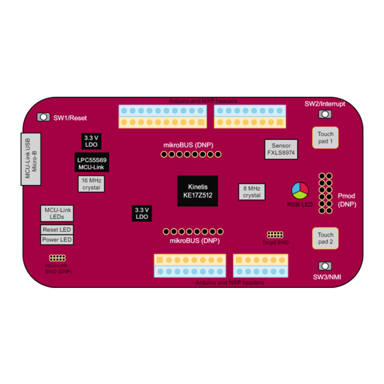
UM12049 NXP Semiconductors FRDM-KE17Z512 Board User Manual 1.4 Board pictures Figure 2 shows the top view of the FRDM-KE17Z512 board. Figure 2. FRDM-KE17Z512 top-side view Target MCU MKE17Z512VLL9 MCU-Link LPC55S69 UM12049 All information provided in this document is subject to legal disclaimers. - Page 5 UM12049 NXP Semiconductors FRDM-KE17Z512 Board User Manual Figure 3 shows the top-side view of the FRDM-KE17Z512 board, with onboard connectors, jumpers, push buttons, and LEDs highlighted. Figure 3. FRDM-KE17Z512 connectors, push buttons, and LEDs (top-side view) Figure 4 shows the bottom view of the FRDM-KE17Z512 board.
-
Page 6: Connectors
UM12049 NXP Semiconductors FRDM-KE17Z512 Board User Manual Figure 4. FRDM-KE17Z512 bottom-side view 1.5 Connectors Connectors are onboard devices that allow you to connect external devices to the board. Figure 3 shows the FRDM-KE17Z512 connectors. Table 3 describes the connectors. Table 3. FRDM-KE17Z512 connectors... -
Page 7: Jumpers
• Shorted (default setting): The MKE17Z512VLL9 MCU is powered 1.7 Push buttons In addition to a Reset button for manually triggering a system reset, the FRDM-KE17Z512 board supports two interrupt push buttons. Figure 3 shows the FRDM-KE17Z512 push buttons. -
Page 8: Leds
Figure 3 shows the FRDM-KE17Z512 LEDs. Table 6 describes the LEDs that correspond to the target MCU. Note: The FRDM-KE17Z512 board also has three status indicator LEDs for MCU-Link. For details, see Section 3.9. Table 6. FRDM-KE17Z512 LEDs Part identifier LED color... -
Page 9: Power Supplies
FRDM-KE17Z512 Board User Manual 2.1 Power supplies The FRDM-KE17Z512 board is powered with a 5 V power supply. The 5 V supply can be sourced from one of the following source options: • P5V_MCU_LINK_USB: External power supply from MCU-Link USB2.0 micro-B connector J10 (default setting). -
Page 10: Clock
FRDM-TOUCH is a touch shield board for FRDM-KE17Z512 with capacitive touch buttons, slider, and rotary. This board can connect with FRDM-KE17Z512 and control the onboard RBG LED using keys, slider, and rotary touches. FRDM-KE17Z512 includes two touch electrodes to support TSI functions in self-capacitive mode. See Table The touch electrode 1 is connected to TSI0 channel 19 and touch electrode 2 is connected to TSI1 channel 3. - Page 11 (TSI) TSI_ELECTRODE2 PTA1/TSI1_CH3-TouchPad_1 Electrode E2 Figure 5. TSI circuit FRDM-KE17Z512 outputs TSI signals to headers J2 and J4 to support the FRDM-TOUCH board. FRDM- TOUCH includes four touch keys in a mutual-capacitive mode, touch slider, and rotary. Table 10. TSI channel connections...
-
Page 12: 3-Axis Digital Sensor
J4[6] CH24 2.4 3-axis digital sensor The FRDM-KE17Z512 board supports an accelerometer sensor to sense motion, a feature required in the IoT application space. The main features of the Accelerometer sensor interface are as follows. • 3-Axis Low-g MEMS accelerometer sensor device FXLS8974CFR3 (U12) is used. -
Page 13: Input/Output Headers
Figure 6. FXLS8974CFR3 sensor circuit 2.5 Input/output headers FRDM-KE17Z512 supports I/O headers that are dual-row headers with the outer rows supporting the Arduino compatible shields and the inner rows supporting the various FRDM shields. These headers are designed to support the following shields: •... - Page 14 UM12049 NXP Semiconductors FRDM-KE17Z512 Board User Manual Table 12. J1 connector (at right-upper side) pinout ...continued I/O header MKE17Z512VLL9 pin / function Arduino / FRDM functions Potential conflict J1[5] PTA8/FXIO_D6 mikroBUS header J5 pin 2 (PTA8/GPIO-MIKROE_INT) J1[6] PTB9 Arduino_D2 Accelerometer sensor voltage...
- Page 15 UM12049 NXP Semiconductors FRDM-KE17Z512 Board User Manual Table 13. J2 connector (at left-upper side) pinout ...continued I/O header MKE17Z512VLL9 pin / function Arduino / FRDM functions Potential conflict J2[10] PTE1/LPSPI0_SIN Arduino_D12 J2[11] PTE11/TSI0_CH9 TOUCH_M_RX_0/GES_R2 PTD4/TSI1_CH7 (DNP) J2[12] PTE0/LPSPI0_SCK Arduino_D13 J2[13] PTC5/TSI0_CH8...
-
Page 16: Mikrobus Interface
FRDM-KE17Z512 supports mikroBUS interface to communicate with the mikroBUS socket board. Table 16 explains the pinout of the mikroBUS headers J5 and J6 on FRDM-KE17Z512. Note: In case the mikroBUS socket board is a 3.3 V device, ensure to switch the power supply of MKE17Z512VLL9 to 3.3 V using J8 jumper. -
Page 17: Pmod Interface
P3V3 J6[8] 2.7 Pmod interface FRDM-KE17Z512 supports a Pmod interface to communicate with the Pmod connector board. Note: If the Pmod connector board is a 3.3 V device, ensure to switch the power supply of the KE17Z512 MCU to 3.3 V using the J8 jumper. -
Page 18: Board Operating Conditions
J11[12] 2.8 Board operating conditions The operating temperature range for the FRDM-KE17Z512 board is -40 ℃ to +105 ℃. The MKE17Z512VLL9 device supports up to 125 ℃ junction temperature. See Kinetis KE17Z/13Z/12Z with up to 512 KB Flash for more details on device operating conditions. -
Page 19: Supported Debug Scenarios
J-Link firmware does not support this feature. 3.3 Supported debug scenarios In the FRDM-KE17Z512 board, the MCU-Link debug probe target can be either the MKE17Z512VLL9 MCU or an external target compliant with MCU-Link. The board also allows to use an external debugger for debugging the MKE17Z512VLL9 MCU, in place of the MCU-Link debug probe. -
Page 20: Updating Mcu-Link Firmware
UM12049 NXP Semiconductors FRDM-KE17Z512 Board User Manual If you do not use the Linkserver utility, follow the steps below to install the firmware MCU-Link update utility and information files: 1. Visit the board page on the NXP website. 2. Go to the Design Resources > Software section. Under the Development Software category, MCU-Link installation packages for Windows, MacOS, and Linux platforms are available. -
Page 21: Using Mcu-Link With Mcuxpresso Ide
CMSIS-DAP probes or J-Link probes (depending on the firmware image you are using.) 3.7 MCU-Link USB connector The FRDM-KE17Z512 board has a Micro-B USB 2.0 connector J10. This USB connector is used to create MCU-Link high-speed USB connection with the host computer. The MCU-Link receives power when the USB connector J10 is plugged into a USB host. -
Page 22: Board Errata
FRDM-KE17Z512. Some of the documents listed below are available only under a nondisclosure agreement (NDA). To request access to these documents, contact your local field applications engineer (FAE) or sales representative. -
Page 23: Acronyms
UM12049 NXP Semiconductors FRDM-KE17Z512 Board User Manual Table 22. Related documentation ...continued Document Title Description How to access LPC55S6x/LPC55S2x/ Intended for system UM11126.pdf LPC552x User manual software and (UM11126) hardware developers and application programmers who want to develop products with LPC55S6x/... -
Page 24: Revision History
UM12049 NXP Semiconductors FRDM-KE17Z512 Board User Manual 7 Revision history Table 24 summarizes the revisions to this document. Table 24. Revision history Document ID Release date Description UM12049 v1.0 15 April 2024 Initial public release UM12049 All information provided in this document is subject to legal disclaimers. -
Page 25: Legal Information
NXP Semiconductors. In the event that customer uses the product for design-in and use in In no event shall NXP Semiconductors be liable for any indirect, incidental, automotive applications to automotive specifications and standards, punitive, special or consequential damages (including - without limitation - customer (a) shall use the product without NXP Semiconductors’... - Page 26 UM12049 NXP Semiconductors FRDM-KE17Z512 Board User Manual AMBA, Arm, Arm7, Arm7TDMI, Arm9, Arm11, Artisan, big.LITTLE, eIQ — is a trademark of NXP B.V. Cordio, CoreLink, CoreSight, Cortex, DesignStart, DynamIQ, Jazelle, IAR — is a trademark of IAR Systems AB. Keil, Mali, Mbed, Mbed Enabled, NEON, POP, RealView, SecurCore, i.MX —...
-
Page 27: Table Of Contents
UM12049 NXP Semiconductors FRDM-KE17Z512 Board User Manual Contents Overview ............2 Block diagram ............2 Board features ........... 2 Kit contents ............3 Board pictures ........... 4 Connectors ............6 Jumpers ............. 7 Push buttons ............7 LEDs ..............8 Functional description ........8 Power supplies ..........
Need help?
Do you have a question about the FRDM-KE17Z512 and is the answer not in the manual?
Questions and answers