Table of Contents
Advertisement
Quick Links
UM11777
FRDMGD3160HB8EVM half-bridge evaluation board
Rev. 1 — 6 May 2022
Document information
Information
Content
Keywords
automotive, half-bridge, GD3160, gate driver
Abstract
This document describes key features and usage requirements for performing
evaluation of GD3160 gate driver with FRDMGD3160HB8EVM.
User manual
Advertisement
Table of Contents

Subscribe to Our Youtube Channel
Related Manuals for NXP Semiconductors SAFE ASSURE FRDMGD3160HB8EVM


Summary of Contents for NXP Semiconductors SAFE ASSURE FRDMGD3160HB8EVM
- Page 1 UM11777 FRDMGD3160HB8EVM half-bridge evaluation board Rev. 1 — 6 May 2022 User manual Document information Information Content Keywords automotive, half-bridge, GD3160, gate driver Abstract This document describes key features and usage requirements for performing evaluation of GD3160 gate driver with FRDMGD3160HB8EVM.
- Page 2 UM11777 NXP Semiconductors FRDMGD3160HB8EVM half-bridge evaluation board Revision history Date Description 20220506 initial version UM11777 All information provided in this document is subject to legal disclaimers. © NXP B.V. 2022. All rights reserved. User manual Rev. 1 — 6 May 2022...
-
Page 3: Important Notice
UM11777 NXP Semiconductors FRDMGD3160HB8EVM half-bridge evaluation board Important notice IMPORTANT NOTICE For engineering development or evaluation purposes only NXP provides the product under the following conditions: This evaluation kit is for use of ENGINEERING DEVELOPMENT OR EVALUATION PURPOSES ONLY. It is provided as a sample IC pre-soldered to a printed-circuit board to make it easier to access inputs, outputs and supply terminals. -
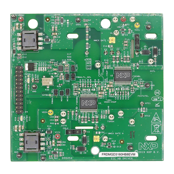
Page 4: Frdmgd3160Hb8Evm
UM11777 NXP Semiconductors FRDMGD3160HB8EVM half-bridge evaluation board FRDMGD3160HB8EVM Figure 1. FRDMGD3160HB8EVM UM11777 All information provided in this document is subject to legal disclaimers. © NXP B.V. 2022. All rights reserved. User manual Rev. 1 — 6 May 2022 4 / 39... -
Page 5: Getting Started
UM11777 NXP Semiconductors FRDMGD3160HB8EVM half-bridge evaluation board Getting started NXP analog product development boards provide a platform for evaluating a broad range of NXP analog, mixed-signal, and power solution products. NXP analog product development boards incorporate monolithic integrated circuits and system-in-package devices that use proven high-volume technology. -
Page 6: Required Equipment
UM11777 NXP Semiconductors FRDMGD3160HB8EVM half-bridge evaluation board 3.2 Required equipment The kit requires the following equipment: • Compatible P6 SiC module • DC link capacitor compatible with the SiC module • 30 µH to 50 µH, high current air core inductor for double pulse testing •... -
Page 7: Device Features
UM11777 NXP Semiconductors FRDMGD3160HB8EVM half-bridge evaluation board 4.3 Device features Table 1. Device features Device Description Features GD3160 The GD3160 is an • Compatible with current sense and temp sense advanced single IGBTs channel gate driver for • DESAT detection capability for detecting V IGBT and SiC. -
Page 8: Low-Voltage Logic And Control Connector
UM11777 NXP Semiconductors FRDMGD3160HB8EVM half-bridge evaluation board Figure 2. Connecting FRDM-KL25Z, FRDMGD3160HB8EVM and KITGD316xTREVB translator board 4.4.1 Low-voltage logic and control connector The low-voltage domain is 12 V VSUP domain that interfaces with the MCU and GD3160 control registers through the 24-pin connector interface. - Page 9 UM11777 NXP Semiconductors FRDMGD3160HB8EVM half-bridge evaluation board Figure 3. FRDMGD3160HB8EVM board voltage and interface domains Table 2. Low-voltage domain 24-pin connector definitions Name Function AOUTL analog output duty cycle encoded signal (low side) for reading temperature via TSENSEA or voltage via AMUXIN n.c.
-
Page 10: Test Point Definitions
UM11777 NXP Semiconductors FRDMGD3160HB8EVM half-bridge evaluation board Table 2. Low-voltage domain 24-pin connector definitions ...continued Name Function MOSIH master out slave in (high side) n.c. not connected CSBH chip select bar (high side) LED_PWR USB 3.3 V power for INTB LEDs (high side and low side) - Page 11 UM11777 NXP Semiconductors FRDMGD3160HB8EVM half-bridge evaluation board Table 3. Test point definitions Name Test Point Definition Low-voltage domain grounding point for low-voltage domain VSUP TP26 DC voltage source connection point for VSUP power input of GD3160 devices; typically supplied by vehicle battery +12 V DC...
-
Page 12: Power Supply And Jumper Configuration
UM11777 NXP Semiconductors FRDMGD3160HB8EVM half-bridge evaluation board 4.4.3 Power supply and jumper configuration Figure 5. Power supply and jumper configuration Table 4. Jumper definitions Jumper Position Function PWMALTL_SEL (J4) dead time fault protection enabled (high side) dead time fault protection disabled (use for short-circuit testing) PS_EN (J2) 1–2... -
Page 13: Bottom View
UM11777 NXP Semiconductors FRDMGD3160HB8EVM half-bridge evaluation board Table 5. Power supply definition Component Definition Flyback MOSFET AEC Q101-compliant logic level N-channel MOSFET (Q1) Potentiometer (R32) adjusts resistor R3 for VCCH/VCCL and VEEH/VEEL tune VCC-GNDISO for +17 V 4.4.4 Bottom view Figure 6. FRDMGD3100HB8EVM bottom view UM11777 All information provided in this document is subject to legal disclaimers. -
Page 14: Gate Drive Resistors
UM11777 NXP Semiconductors FRDMGD3160HB8EVM half-bridge evaluation board 4.4.5 Gate drive resistors • RGH - gate high resistor in series with the GH pin at the output of the GD3160 gate high driver and P6 SiC module gate that controls the turn-on current for SiC MOSFET gate. -
Page 15: Led Interrupt Indicators
UM11777 NXP Semiconductors FRDMGD3160HB8EVM half-bridge evaluation board 4.4.6 LED interrupt indicators Figure 8. LED interrupt indicators Table 6. LED interrupt indicators Description Low-side INTB connected to the INTB output pin of low-side driver indicating reported fault status when on (active LOW) High-side INTB... -
Page 16: Kinetis Kl25Z Freedom Board
UM11777 NXP Semiconductors FRDMGD3160HB8EVM half-bridge evaluation board 4.5 Kinetis KL25Z Freedom board The Freedom KL25Z is an ultra low-cost development platform for Kinetis L series MCU built on Arm Cortex-M0+ processor. Figure 9. Freedom development platform UM11777 All information provided in this document is subject to legal disclaimers. -
Page 17: To 5.0 V Translator Board
UM11777 NXP Semiconductors FRDMGD3160HB8EVM half-bridge evaluation board 4.6 3.3 V to 5.0 V translator board KITGD316xTREVB translator enables level shifting of signals from MCU 3.3 V to 5.0 V SPI communication. Figure 10. Translator board Table 7. Translator board jumper definitions Jumper... - Page 18 UM11777 NXP Semiconductors FRDMGD3160HB8EVM half-bridge evaluation board Suggested equipment needed for test: • Rogowski coil high-current probe • High-voltage differential voltage probe • High sample rate digital oscilloscope with probes • DC link capacitor • SiC MOSFET P6 module • Windows based PC •...
-
Page 19: Installation And Use Of Software Tools
UM11777 NXP Semiconductors FRDMGD3160HB8EVM half-bridge evaluation board Installation and use of software tools Software for FRDMGD3160HB8EVM is distributed with the FlexGUI tool (available on NXP.com). Necessary firmware comes pre-installed on the FRDM-KL25Z with the kit. Even if the user intends to test with other software or PWM, it is recommended to install this software as a backup or to help debugging. -
Page 20: Using The Flexgui
UM11777 NXP Semiconductors FRDMGD3160HB8EVM half-bridge evaluation board 1. To clear the memory and place the board in boot loader mode, hold down the reset button while plugging a USB cable into the OpenSDA USB port. 2. Verify that the board appears as a BOOTLOADER device and continue with step 3. If the board appears as KL25Z, you may go to step 6. - Page 21 UM11777 NXP Semiconductors FRDMGD3160HB8EVM half-bridge evaluation board Figure 13. Kit selection FlexGUI settings • Access settings by selecting Settings from the File menu Figure 14. GUI settings menu UM11777 All information provided in this document is subject to legal disclaimers. © NXP B.V. 2022. All rights reserved.
- Page 22 UM11777 NXP Semiconductors FRDMGD3160HB8EVM half-bridge evaluation board • The Loader and Logs settings are shown below: Figure 15. Loader settings Figure 16. Logs settings UM11777 All information provided in this document is subject to legal disclaimers. © NXP B.V. 2022. All rights reserved.
- Page 23 UM11777 NXP Semiconductors FRDMGD3160HB8EVM half-bridge evaluation board • Access settings by selecting Settings from the File menu. • The Register Map and Tabs settings are shown below: Figure 17. Register map settings Figure 18. Tabs settings UM11777 All information provided in this document is subject to legal disclaimers.
- Page 24 UM11777 NXP Semiconductors FRDMGD3160HB8EVM half-bridge evaluation board Command Log window • The Command Log area informs the user about application events. Figure 19. Command Log area UM11777 All information provided in this document is subject to legal disclaimers. © NXP B.V. 2022. All rights reserved.
- Page 25 UM11777 NXP Semiconductors FRDMGD3160HB8EVM half-bridge evaluation board Global workspace controls • Always visible in the lower left corner of the main application window. – GD3160 tab functionality – Switch modes between run and configuration mode – Set SPI frequency – Check pin status and clear faults if needed –...
- Page 26 UM11777 NXP Semiconductors FRDMGD3160HB8EVM half-bridge evaluation board • Status tab functionality – Monitors Status 1 and Status 2 fault bits. Bits that are set are shown in red. – Ability to clear all faults and automatically poll status registers. Figure 22. Status tab functionality •...
- Page 27 UM11777 NXP Semiconductors FRDMGD3160HB8EVM half-bridge evaluation board Register map • Registers are grouped according to function; independent lines to read and write the registers • Individual registers can be read by clicking the R button and can be written by using the W button.
- Page 28 UM11777 NXP Semiconductors FRDMGD3160HB8EVM half-bridge evaluation board Gate Drive tab • Allows setting of parameters related to the gate drive; controls are disabled when not in config mode • Provides a more intuitive visual way to set parameters • All settings are automatically synchronized with the register controls.
- Page 29 UM11777 NXP Semiconductors FRDMGD3160HB8EVM half-bridge evaluation board Current Sense tab • Allows setting of parameters related to current sense • Provides a more intuitive visual way to set parameters • All settings are automatically synchronized with the register controls. Figure 26. Current sense tab UM11777 All information provided in this document is subject to legal disclaimers.
- Page 30 UM11777 NXP Semiconductors FRDMGD3160HB8EVM half-bridge evaluation board DESAT & Seg Drive tab • Allows setting of parameters related to desat and segmented drive • Provides a more intuitive visual way to set parameters • All settings are automatically synchronized with the register controls.
- Page 31 UM11777 NXP Semiconductors FRDMGD3160HB8EVM half-bridge evaluation board Overtemperature tab • Allows setting of parameters related to overtemperature and overtemperature warning thresholds • Provides a more intuitive visual way to set parameters • All settings are automatically synchronized with the register controls.
- Page 32 UM11777 NXP Semiconductors FRDMGD3160HB8EVM half-bridge evaluation board Measurements tab • Allows monitoring and graphing of ADC and temperature values Figure 30. Measurements tab UM11777 All information provided in this document is subject to legal disclaimers. © NXP B.V. 2022. All rights reserved.
- Page 33 UM11777 NXP Semiconductors FRDMGD3160HB8EVM half-bridge evaluation board Status tab • Allows monitoring of Status 1, Status 2, and Status 3 register values • Status 1 and Status 2 faults can be cleared • Status mask registers can be modified when in configuration mode •...
-
Page 34: Troubleshooting
UM11777 NXP Semiconductors FRDMGD3160HB8EVM half-bridge evaluation board 6.4 Troubleshooting Some common issues and troubleshooting procedures are detailed below. This is not an exhaustive list by any means, and additional debug may be needed: Problem Evaluation Explanation Corrective action(s) No PWM output (no fault reported) -
Page 35: Schematics, Board Layout, And Bill Of Materials
UM11777 NXP Semiconductors FRDMGD3160HB8EVM half-bridge evaluation board Problem Evaluation Explanation Corrective action(s) SPIERR reported after SPI message Check bit length of message sent There is SPIERR if SCLK does not Use 24-bit message length for SPI see a n*24 multiple of cycles... -
Page 36: Legal Information
NXP Semiconductors. In no event shall NXP Semiconductors be liable for any indirect, incidental, Evaluation products — This product is provided on an “as is” and “with all punitive, special or consequential damages (including - without limitation - faults”... - Page 37 UM11777 NXP Semiconductors FRDMGD3160HB8EVM half-bridge evaluation board NXP — wordmark and logo are trademarks of NXP B.V. 9.3 Trademarks Kinetis — is a trademark of NXP B.V. SafeAssure — is a trademark of NXP B.V. Notice: All referenced brands, product names, service names, and trademarks are the property of their respective owners.
- Page 38 UM11777 NXP Semiconductors FRDMGD3160HB8EVM half-bridge evaluation board Tables Tab. 1. Device features ..........7 Tab. 4. Jumper definitions ........... 12 Tab. 2. Low-voltage domain 24-pin connector Tab. 5. Power supply definition ........13 definitions ............9 Tab. 6. LED interrupt indicators ........15 Tab.
-
Page 39: Table Of Contents
UM11777 NXP Semiconductors FRDMGD3160HB8EVM half-bridge evaluation board Contents Important notice ..........3 FRDMGD3160HB8EVM ........4 Getting started ............ 5 Kit contents/packing list ........5 Required equipment .......... 6 System requirements .........6 Getting to know the hardware ......6 Overview ............6 Board features ...........
Need help?
Do you have a question about the SAFE ASSURE FRDMGD3160HB8EVM and is the answer not in the manual?
Questions and answers