
Related Manuals for NXP Semiconductors FRDM-KL46Z


Summary of Contents for NXP Semiconductors FRDM-KL46Z
- Page 1 FRDM-KL46Z User’s Manual FRDM-KL46Z-UM Rev. 1.0 Freescale Semiconductor Inc. Microcontroller Solutions Group...
-
Page 2: Table Of Contents
1 FRDM-KL46Z Overview ......................... 3 2 References documents .......................... 3 3 Getting started ............................3 4 FRDM-KL46Z Hardware Overview ....................4 5 FRDM-KL46Z Hardware Description ....................7 5.1.1 Power Supply ....................................... 7 5.1.2 Serial and Debug Adapter (OpenSDA) ............................9 5.1.3 Clock source ....................................... -
Page 3: Frdm-Kl46Z Overview
ARM® Cortex™-M0+ core. FRDM-KL46Z can be used to evaluate the KL46, KL36, KL26 and KL16 Kinetis L series devices. It features a MKL46Z256VLL4, this device boasting a max operating frequency of 48MHz, 256KB of flash, 32KB RAM, a full- speed USB controller, segment LCD controller, and loads of analog and digital peripherals. -
Page 4: Frdm-Kl46Z Hardware Overview
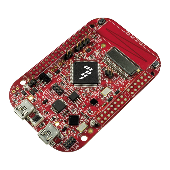
CMSIS-DAP interface: new ARM standard for embedded debug interface o Data logging application Arduino R3 compatibility Figure 1 shows a block diagram of the FRDM-KL46Z design. The primary components and their placement on the hardware assembly are pointed out in Figure 2. Freescale Semiconductor, Inc FRDM-KL46Z... - Page 5 Figure 1. FRDM-KL46Z block diagram Freescale Semiconductor, Inc FRDM-KL46Z Page 5 of 17...
- Page 6 Figure 2. FRDM-KL46Z main components placement . Freescale Semiconductor, Inc FRDM-KL46Z Page 6 of 17...
-
Page 7: Frdm-Kl46Z Hardware Description
5 FRDM-KL46Z Hardware Description 5.1.1 Power Supply There are multiple power supply options on the FRDM-KL46Z. It can be powered from either of the USB connectors, the V pin on the I/O header, an on-board coin cell battery, or an off-board 1.71-3.6V supply from the 3.3V pin on the I/O header. - Page 8 Coin cell battery supply voltage. Sources power to the P3V3 supply rail through a back drive protection Schottky diode. P3V3 Main supply rail for FRDM-KL46Z assembly. May be sourced from P3V3_VREG, P3V3_BATT, or directly from the I/O headers (J9 pin P3V3_KL46Z KL46Z MCU supply.
-
Page 9: Serial And Debug Adapter (Opensda)
PCB that connects J18 pin 2 to J11 pin 2. This will disconnect the SWD_CLK pin to the KL46 so that it will not interfere with the communications to an off-board MCU connected to J11. Freescale Semiconductor, Inc FRDM-KL46Z Page 9 of 17... - Page 10 USB host and this serial interface on the K20. 5.3 MKL46Z4 Microcontroller The target microcontroller of the FRDM-KL46Z is the KL462Z256VLL4, a Kinetis L series device in an 100 LQFP package. The KL46Z MCU features include:. ...
- Page 11 Low-power Timer (LPT) o System tick timer Human-Machine Interfaces (HMI) o Segment LCD controller. Maximum segment is 8X47 or 4x51. o General purpose input/output controller o Capacitive touch sense input interface hardware module Freescale Semiconductor, Inc FRDM-KL46Z Page 11 of 17...
-
Page 12: Clock Source
The sole debug interface on all Kinetis L Series devices is a Serial Wire Debug (SWD) port. The primary controller of this interface on the FRDM-KL46Z is the onboard OpenSDA circuit (see section 5.2). However, an unpopulated 10-pin (0.05”) Cortex Debug connector, J11, provides access to the SWD signals. The Samtec FTSH-105-02-F-D or compatible connectors can be added to the J11 through-hole debug connector to allow for an external debug cable to be connected. -
Page 13: Capacitive Touch Slider
FRDM-KL46Z is using a 4 digit display (LUMEX LCD-S401M16KR) 4x8 segments. following table shows connection from KL46 to s401 display. Table 4. sLCD connections s401 pin KL46 LCD Pin LCD_P40 (COM0) LCD_P52 (COM1) LCD_P19 (COM2) LCD_P18 (COM3) LCD_P37 LCD_P17 LCD_P7... -
Page 14: Three-Axis Digital Magnetometer
PTD1 (shared with INT2_ACCEL) can be isolated removing R50 5.1.12 LEDs Two LED, Green LED is PWM capable, Signal connections are shown in Table 7. Table 7. LED Signal Connections KL46 PTD5 Green PTE29/TPM0_CH2 Freescale Semiconductor, Inc FRDM-KL46Z Page 14 of 17... -
Page 15: Visible Light Sensor
5.1.13 Visible light sensor The FRDM-KL46Z has a visible light sensor that is connected to ADC0_SE3 PTE22/ADC0_DP3/ADC0_SE3/ Figure 7 Visible light sensor schematic Freescale Semiconductor, Inc FRDM-KL46Z Page 15 of 17... -
Page 16: Input/Output Connectors
Port A is referred to as PTA1. The I/O connector pin names are given the same name as the KL46 pin connected to it, where applicable. Figure 8 FRDM-KL46 Pin-Out Freescale Semiconductor, Inc FRDM-KL46Z Page 16 of 17... -
Page 17: Arduino Compatibility
Note that all pinout data is available in spreadsheet format in FRDM-KL46Z Pinouts. See the Reference Documents section for details. 5.1.15 Arduino Compatibility The I/O headers on the FRDM-KL46Z are arranged to allow compatibility with peripheral boards (known as shields) that connect to Arduino™ and Arduino-compatible microcontroller boards. The outer rows of pins (the even numbered pins) on the headers share the same mechanical spacing and placement as the I/O headers on the Arduino Revision 3 (R3) standard.
Need help?
Do you have a question about the FRDM-KL46Z and is the answer not in the manual?
Questions and answers