Advertisement
Quick Links
DESCRIPTION
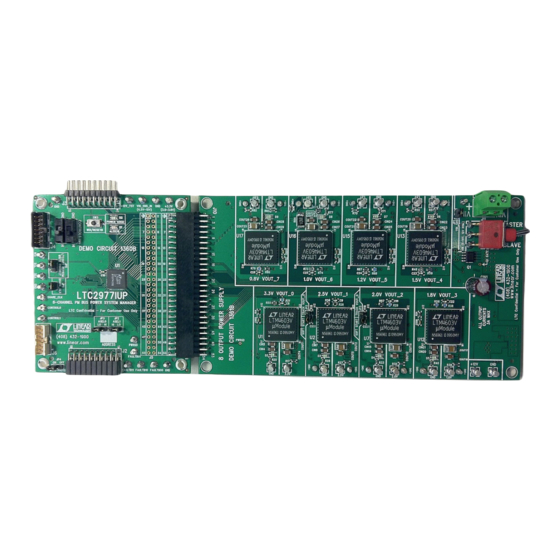
The DC1540B is a demonstration system for the
2
8-channel I
C/SMBus/PMBus Power System Manager
with EEPROM. It consists of 2 circuit boards namely the
DC1360B and DC1361B. The DC1360B contains all the
circuitry needed to insert the LTC2977 into a power system
and control eight power supplies. The DC1361B contains
eight power supplies (LTM4603EV) which are configured
to be controlled by an LTC2977. Together these two boards
form a sophisticated, 8-channel, digitally programmable
power supply.
This demonstration system is supported by LTpowerPlay™
software and a graphical user interface (GUI) that enables
complete control of all the LTC2977 features. You can obtain
this GUI from the website www.linear.com/ltpowerplay.
com. LTpowerPlay and the DC1540B, create a powerful
development environment in which you can design config-
uration settings for the LTC2977. The configuration settings
can be stored in the LTC2977 EEPROM and also in a file,
which can be used to order pre-programmed devices.
LTpowerPlay displays all of the configuration settings and
real-time measurements that the LTC2977 performs and
allows easy access to the fault log created by the LTC2977.
The LTC2977 on the DC1360B comes pre-programmed with
EEPROM values appropriate for the eight power supplies
used on the DC1361B.
The LTC2977 can be configured to monitor current
on odd numbered channels. In the DC1540B, this
feature can be enabled on Channel 7 (see "Measur-
ing Current"). Channels 1 and 2 can be configured
to do coincident tracking of Channel 0 by using JP2
and JP3 (see "DC1361B Details – Top Side"). An LTC
Hot Swap™ circuit on the DC1361B enables the LTC2977 to
soft-start V
and shut off V
IN
Multiple DC1540Bs can be cascaded together to form
a high channel count power supply (see "Multi-Board
Arrays"). This configuration demonstrates features of the
LTC2977 which allow timing and fault information to be
LTC
2977
®
in response to output faults.
IN
DEMO MANUAL DC1540B
LTC2977 8-Channel
Power System Manager
shared across multiple LTC2977s, allowing the formation
of a single, coherent power supply control system. This
configuration is easily supported by the LTpowerPlay
GUI and allows the user to configure up to 9 LTC2977s,
controlling up to 72 separate power supplies.
To get this demo system up and running, connect the
DC1540B to your computer using a DC1427A or a DC1613
2
(USB to I
C/SMBus/PMBus Controller). The following is
a checklist of items which you can obtain from the LTC
website or LTC Field Sales.
2
USB to I
C/SMBus/PMBus Controller (DC1613A)
n
LTpowerPlay GUI
n
LTC2977 Resistor Selection Tool for calculating
n
resistors values and proper DAC range settings
(in the GUI)
LTC2977 Features
2
• I
C/SMBus Communication
• Configuration EEPROM
• PMBus Compliant
• Fault Logging to Internal EEPROM
• Differential Input, 16-bit ∆S ADC with less than ±0.25%
of Total Unadjusted Error Using On-Chip Reference
• Monitors Eight Output Channels and One Input Voltage
• Programmable Watchdog Timer
• 8-Channel Sequencer
• Eight 10-Bit OV/UV Supervisors
• Eight 10-Bit Margin/Trim DAC's with Soft-Connect
• A Closed-Loop Digital Servo Accurately Trims the Outputs
• Supports Multi-Channel Fault Management
• Programmable Fault Responses
• On-Chip Digital Temperature Sensor
Design files for this circuit board are available at
http://www.linear.com/demo
L, LT, LTC, LTM, Linear Technology, and the Linear logo are registered trademarks and
LTpowerPlay and Hot Swap are trademarks of Linear Technology Corporation. All other
trademarks are the property of their respective owners.
with EEPROM
dc1540bf
1
Advertisement

Related Manuals for Linear Technology DC1540B


Summary of Contents for Linear Technology DC1540B
- Page 1 Multiple DC1540Bs can be cascaded together to form a high channel count power supply (see “Multi-Board L, LT, LTC, LTM, Linear Technology, and the Linear logo are registered trademarks and LTpowerPlay and Hot Swap are trademarks of Linear Technology Corporation. All other Arrays”).
- Page 2 DEMO MANUAL DC1540B Table 1. LTC2977 Performance Summary (Specifications are at T = 25°C) PARAMETER CONDITION VALUE Supply Input Voltage Range 4.5V to 15V Supply Input Voltage Range 3.13V to 3.47V DD33 ADC Total Unadjusted Error ≥ 1V ±0.25% ADC Voltage Sensing Input Range –0.1V to 6V...
- Page 3 4. DC1540B = DC1360B + DC1361B • Test most conceivable fault scenarios. All outputs can be shorted. Figure 1. Single LTC2977 Demo Setup Using DC1540B DOWNLOAD GUI TO YOUR PC LTpowerPlay can be downloaded from www.linear.com/ltpowerplay. Complete instructions are located there.
-
Page 4: Quick Start Procedure
DEMO MANUAL DC1540B QUICK START PROCEDURE The following procedure describes how to set up one DC1540B. 1. Remove both boards from bag. 2. Place boards on level surface. Connect boards together using the 54-pin edge connector. See below. Figure 2. Plug Boards Together 3. - Page 5 DEMO MANUAL DC1540B QUICK START PROCEDURE Figure 3. DC1427A Connection Figure 4. DC1613 Connection dc1540bf...
- Page 6 DEMO MANUAL DC1540B QUICK START PROCEDURE 8. Launch the LTpowerPlay GUI. a. The GUI should identify the LTC2977. The system tree on the left hand side should look like: b. Confirm that the LTC2977 is communicating. A green message box shows for a few seconds in the lower left hand corner c.
- Page 7 DEMO MANUAL DC1540B QUICK START PROCEDURE The System Tree on the left hand side should turn all green. All 8 green LEDs on the DC1361B should illuminate. 11. You are now ready to execute one of the LTC2977 demos embedded in the GUI or experiment with the part.
- Page 8 DEMO MANUAL DC1540B DC1540B - DETAILS (DC1360B +DC1361B) Figure 5. DC1540B Details dc1540bf...
- Page 9 DEMO MANUAL DC1540B DC1360B DETAILS - TOP SIDE Figure 6. DC1360B Top Side Table 3. DC1360B - Default Jumper Configuration. Use ASEL’s to Select I C Address. ASEL1 ASEL0 Write-Protect LTC2977 Write Share_CLK Protect Installed dc1540bf...
- Page 10 DEMO MANUAL DC1540B DC1360B DETAILS - BOTTOM SIDE Figure 7. DC1360B Bottom Side Configuration Resistors Configuration resistors are on the bottom side. They allow multiple ways to make fault dependencies between boards. Table 4. Optional Configuration Resistors REF Des Signal...
- Page 11 DEMO MANUAL DC1540B DC1360B DETAILS - BOTTOM SIDE Setting the Device Address the PMBus Alert Response address regardless of the state of the address select pins. The LTC2977 can be configured to respond to one of 9 addresses for a given MFR_I...
- Page 12 DEMO MANUAL DC1540B DC1361B DETAILS - TOP SIDE Figure 8. DC1361B Top Side Table 6. DC1361B - Default Jumper and Switch Configurations Track V /Soft-Start Track V /Soft-Start IN_SNS OUT_0 OUT_0 Installed = Master Removed = Slave Soft-Start Soft-Start Master...
- Page 13 DEMO MANUAL DC1540B DC1361B - CHANGING THE NOMINAL OUTPUT VOLTAGES Figure 9. DC1361B Output Voltage Setting Resistor Locations The Nominal V of any channel on the DC1361B can be See also the LTM4603 datasheet Table 2. V may be OUT0...
- Page 14 DEMO MANUAL DC1540B DC1361B – ADJUSTING THE MARGIN/TRIM RANGE AND RESOLUTION OF THE OUTPUT VOLTAGES The resolution and range can be adjusted for any output The design tool refers to R30. This is the margin/trim on the DC1361B by simply replacing the below resistors.
-
Page 15: Measuring Current
DEMO MANUAL DC1540B MEASURING CURRENT It is possible to measure the current on Channel 6 by using One simple checkbox in the GUI sets up Channel 7 to mea- Channel 7 in “Hi Res” mode. Follow the instructions on sure current. In the MFR_CONFIG_LTC2977 register check pp.9 and 10 of DC1361B schematic. - Page 16 DEMO MANUAL DC1540B COMMON DEMO BOARD OPERATIONS Reset the LTC2977 Faulting an Output To reset the LTC2977 and reload the EEPROM contents Use a jumper wire or a coin to short any output. For an OV into operating memory (RAM), press SW3.
- Page 17 DEMO MANUAL DC1540B FAULT ZONE CONFIGURATION AND FAULT PROPAGATION The LTC2977 has four FAULTB pins within two fault zones. to other DC1360B’s in a multiboard array. Therefore, it is Each channel can pull FAULTB pins within its zone low. possible for any channel in an array to shutoff in response Also, any channel can shutdown in response to FAULTB to any other channel.
- Page 18 DEMO MANUAL DC1540B SETUP PROCEDURE FOR MULTI-BOARD ARRAYS Multiple DC1540Bs can be combined to control as many 5. Set the Master/Slave switch on the first DC1361B in output voltages as desired. the array to Master. Set other boards to Slave.
-
Page 19: Parts List
DEMO MANUAL DC1540B PARTS LIST ITEM QTY REFERENCE PART DESCRIPTION MANUFACTURER/PART NUMBER Required Circuit Components IC 8-CH PWR SYSTEM MANAGER 64-QFN LINEAR TECH: LTC2977IUP C8, C9, C10 CAP CERM 0.1µF 16V 20% X7R 0603 AVX: 0603YC104MAT2A R1, R2, R4, R5, R11, R75... - Page 20 DEMO MANUAL DC1540B SCHEMATIC DIAGRAM dc1540bf...
- Page 21 DEMO MANUAL DC1540B SCHEMATIC DIAGRAM dc1540bf...
- Page 22 DEMO MANUAL DC1540B SCHEMATIC DIAGRAM dc1540bf...
- Page 23 DEMO MANUAL DC1540B SCHEMATIC DIAGRAM dc1540bf...
- Page 24 DEMO MANUAL DC1540B PARTS LIST ITEM REFERENCE PART DESCRIPTION MANUFACTURER/PART NUMBER Required Circuit Components DC1361B is only a companion board to the DC1360B. None of these parts are required for LTC2977 operation. Additional Demo Board Circuit Components CAP CER 1000pF 50V 10% X7R 0603...
- Page 25 DEMO MANUAL DC1540B SCHEMATIC DIAGRAM ITEM REFERENCE PART DESCRIPTION MANUFACTURER/PART NUMBER RES 19.1k 1/10W 1% 0603 SMD VISHAY: CRCW060319K1FKEA R86, R87 (OPT.) RES 0.0Ω 1/10W 5% 0603 SMD VISHAY: CRCW06030000Z0EA R88, R89 RES 0.0Ω 1/10W 5% 0603 SMD VISHAY: CRCW06030000Z0EA R91, R112 RES 60.4k 1/10W 1% 0603 SMD...
- Page 26 DEMO MANUAL DC1540B SCHEMATIC DIAGRAM dc1540bf...
- Page 27 DEMO MANUAL DC1540B SCHEMATIC DIAGRAM dc1540bf...
- Page 28 DEMO MANUAL DC1540B SCHEMATIC DIAGRAM dc1540bf...
- Page 29 DEMO MANUAL DC1540B SCHEMATIC DIAGRAM dc1540bf...
- Page 30 DEMO MANUAL DC1540B SCHEMATIC DIAGRAM dc1540bf...
- Page 31 DEMO MANUAL DC1540B SCHEMATIC DIAGRAM dc1540bf...
- Page 32 DEMO MANUAL DC1540B SCHEMATIC DIAGRAM dc1540bf...
- Page 33 DEMO MANUAL DC1540B SCHEMATIC DIAGRAM dc1540bf...
- Page 34 DEMO MANUAL DC1540B SCHEMATIC DIAGRAM dc1540bf...
- Page 35 Information furnished by Linear Technology Corporation is believed to be accurate and reliable. However, no responsibility is assumed for its use. Linear Technology Corporation makes no representation that the interconnection of its circuits as described herein will not infringe on existing patent rights.
- Page 36 Linear Technology Corporation (LTC) provides the enclosed product(s) under the following AS IS conditions: This demonstration board (DEMO BOARD) kit being sold or provided by Linear Technology is intended for use for ENGINEERING DEVELOPMENT OR EVALUATION PURPOSES ONLY and is not provided by LTC for commercial use. As such, the DEMO BOARD herein may not be complete in terms of required design-, marketing-, and/or manufacturing-related protective considerations, including but not limited to product safety measures typically found in finished commercial goods.
Need help?
Do you have a question about the DC1540B and is the answer not in the manual?
Questions and answers