Advertisement
DESCRIPTION
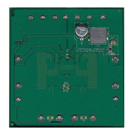
The demo circuit 1537A is a dual current mode PWM
step-down DC/DC converter featuring LT
circuit is designed for 5V and 3.3V outputs from a 7V to
60V input. The current capability of each channel is up to 3A
when running individually and 2A when both are sourcing
the same current without special heat sinking. Individual
soft-start, current limit, comparator, input voltage for each
output as well as frequency division and synchronous
and clock output functions simplify the complex design
of dual-output power converters
Both converters are synchronized to either a common
external clock input or a resistor programmable 250kHz to
2MHz internal oscillator. At all frequencies, a 180° phase
shift between channels is maintained, reducing voltage
ripple. Programmable frequency allows optimization be-
tween efficiency and external component size. Each output
can be independently disabled using its own SHDN pin
and be placed in a low quiescent current shutdown mode.
The LT3992 data sheet gives complete description of the
device, operation and application information. The data
PERFORMANCE SUMMARY
PARAMETER
Minimum Input Voltage
Maximum Input Voltage
Output Voltage V
OUT1
Output Voltage V
OUT2
Switching Frequency
Maximum Output Current I
Maximum Output Current I
Voltage Ripple V
OUT1
Voltage Ripple V
OUT2
Arrow.com.
Downloaded from
®
3992. The demo
CONDITIONS
V
= 7~ 60V
IN
V
= 7~ 60V
IN
V
= 7~ 60V
OUT1
IN
V
= 7~ 60V
OUT2
IN
V
= 12V, I
IN
V
= 12V, I
IN
DEMO MANUAL DC1537A
Monolithic Dual Tracking 3A
Step-Down Switching Regulator
sheet must be read in conjunction with this quick start
guide for demo circuit 1537A.
Design files for this circuit board are available at
http://www.linear.com/demo
100
95
90
85
80
75
70
65
60
Figure 1. Single Channel Efficiency at V
f = 300kHz
L, LT, LTC, LTM, Linear Technology and the Linear logo are registered trademarks of Linear
Technology Corporation. All other trademarks are the property of their respective owners.
Specifi cations are at T
= 25°C.
A
= 3A
OUT1
= 3A
OUT2
V
= 5V
OUT1
V
= 3.3V
OUT2
0.3
1.2
1.5
1.8
2.1
2.4 2.7 3.0
0.6 0.9
LOAD CURRENT FOR SIGNAL CHANNEL (A)
DC1537a F01
VALUE
7V
60V (For Transient. Continuous Operation
if D3 and D4 Are Replaced with Higher
Voltage Rated Schottky Diodes)
5.0V ±3%
3.3V ±3%
300kHz ±10%
3A Individually, 2A Both Running
3A Individually, 2A Both Running
<20mV
<20mV
LT3992A
= 24V,
IN
dc1537af
1
Advertisement
Table of Contents

Subscribe to Our Youtube Channel
Summary of Contents for Linear Technology DC1537A
- Page 1 The LT3992 data sheet gives complete description of the device, operation and application information. The data L, LT, LTC, LTM, Linear Technology and the Linear logo are registered trademarks of Linear Technology Corporation. All other trademarks are the property of their respective owners.
- Page 2 0.4 0.6 LOAD CURRENT FOR BOTH CHANNELS (A) DC1537a F02 DC1537a F03 DC1537a F04 Figure 2. Dual Channel Efficiency Figure 3. DC1537A T Pin Voltage Figure 4. DC1537A T Pin Voltage at V = 24V, f = 300kHz When Channels Running Individually...
- Page 3 DEMO MANUAL DC1537A QUICK START PROCEDURE Figure 5. DC1537A Proper Equipment Setup Figure 6. Measuring Input or Output Ripple Figure 7. Cut Line for the EMI Filter Installation dc1537af Arrow.com. Arrow.com. Arrow.com. Downloaded from Downloaded from Downloaded from...
- Page 4 DEMO MANUAL DC1537A PARTS LIST ITEM REFERENCE PART DESCRIPTION MANUFACTURER/PART NUMBER Required Circuit Components C2, C3, C22, C23 CAP , 1210 2.2μF 10% 100V X7R AVX 12101C225KAT2A C4, C5 CAP , 0603 0.47μF 10% 25V X7R MURATA GRM188R71E474KA12D C7, C8 CAP , 1210 100μF 20% 10V X5R...
- Page 5 Information furnished by Linear Technology Corporation is believed to be accurate and reliable. However, no responsibility is assumed for its use. Linear Technology Corporation makes no representa- tion that the interconnection of its circuits as described herein will not infringe on existing patent rights.
- Page 6 Linear Technology Corporation (LTC) provides the enclosed product(s) under the following AS IS conditions: This demonstration board (DEMO BOARD) kit being sold or provided by Linear Technology is intended for use for ENGINEERING DEVELOPMENT OR EVALUATION PURPOSES ONLY and is not provided by LTC for commercial use. As such, the DEMO BOARD herein may not be complete in terms of required design-, marketing-, and/or manufacturing-related protective considerations, including but not limited to product safety measures typically found in finished commercial goods.


Need help?
Do you have a question about the DC1537A and is the answer not in the manual?
Questions and answers