Advertisement
Quick Links
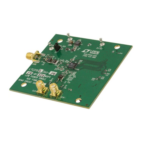
Description
Demonstration circuit 1565A supports a family of
12‑Bit/14‑Bit 170Msps to 310Msps ADCs. Each assem‑
bly features one of the following devices: LTC2153‑14/
LTC2153‑12, LTC2152‑14/LTC2152‑12, LTC2151‑14/
LTC2151‑12, LTC2150‑14/LTC2150‑12, high speed ADCs.
The versions of the 1565A demo board are listed in Table 1.
Depending on the required resolution and sample rate,
the DC1565A is supplied with the appropriate ADC. The
Table 1. DC1565A Variants
DC1565A VARIANTS
1565A‑A
1565A‑B
1565A‑C
1565A‑D
1565A‑E
1565A‑F
1565A‑G
1565A‑H
perForMAnce sUMMArY
PARAMETER
Supply Voltage – DC1565A
Analog Input Range
Logic Input Voltages
Logic Output Voltages (Differential)
Sampling Frequency (Convert Clock Frequency)
Encode Clock Level
Resolution
12-Bit/14-Bit, 170Msps to 310Msps ADCs
ADC PART NUMBER
LTC2152‑14
LTC2151‑14
LTC2150‑14
LTC2152‑12
LTC2151‑12
LTC2150‑12
LTC2153‑14
LTC2153‑12
(T
= 25°C)
A
CONDITIONS
Depending on Sampling Rate and the A/D Converter
Provided, This Supply Must Provide Up to 500mA.
Depending on SENSE Pin Voltage
Minimum Logic High
Maximum Logic Low
Nominal Logic Levels (100Ω Load, 3.5mA Mode)
Common Mode
Minimum Logic Levels (100Ω Load, 3.5mA Mode)
Common Mode
See Table 1
Differential Encode Mode (ENC
See Table 1
DEMO MANUAL DC1565A
LTC2153-14, LTC2153-12,
LTC2152-14, LTC2152-12,
LTC2151-14, LTC2151-12,
LTC2150-14, LTC2150-12
circuitry on the analog inputs is optimized for analog input
frequencies from 5MHz to 140MHz. Refer to the data sheet
for proper input networks for different input frequencies.
Design files for this circuit board are available at
http://www.linear.com/demo
L, LT, LTC, LTM, µModule, Linear Technology and the Linear logo are registered trademarks
and PScope is a trademark of Linear Technology Corporation. All other trademarks are the
property of their respective owners.
RESOLUTION
MAXIMUM SAMPLE RATE
14‑Bit
14‑Bit
14‑Bit
12‑Bit
12‑Bit
12‑Bit
14‑Bit
12‑Bit
–
Not Tied to GND)
INPUT FREQUENCY
250Msps
5MHz to 140MHz
210Msps
5MHz to 140MHz
170Msps
5MHz to 140MHz
250Msps
5MHz to 140MHz
210Msps
5MHz to 140MHz
170Msps
5MHz to 140MHz
310Msps
5MHz to 140MHz
310Msps
5MHz to 140MHz
MIN
TYP
3
3.6
1.5 or 1.32
1.3
0.6
350
1.25
247
1.25
0.2
MAX
UNITS
6
V
V
P‑P
V
V
mV
V
mV
V
1.9
V
dc1565afa
1
Advertisement

Related Manuals for Linear Technology DC1565A


Summary of Contents for Linear Technology DC1565A
- Page 1 The versions of the 1565A demo board are listed in Table 1. L, LT, LTC, LTM, µModule, Linear Technology and the Linear logo are registered trademarks Depending on the required resolution and sample rate, and PScope is a trademark of Linear Technology Corporation. All other trademarks are the property of their respective owners.
-
Page 2: Performance Summary
If a DC1371 Data Acquisition and Collection System was supplied with the DC1565A demonstration circuit, fol‑ low the DC1371 Quick Start Guide to install the required software and for connecting the DC1371 to the DC1565A and to a PC. 3.6V TO 6V... - Page 3 DC1565A demonstration circuit board marked CLK the DC1371 must first be connected to a powered USB As a default the DC1565A is populated to have a single‑ port and have 5V applied power before applying 3.6V to ended input.
- Page 4 DEMO MANUAL DC1565A qUick stArt proceDUre Serial Programming PScope has the ability to program the DC1565A board serially through the DC1371. There are several options available in the LTC2152 family that are only available Figure 2. PScope Toolbar through serially programming. PScope allows all of these features to be tested.
- Page 5 DEMO MANUAL DC1565A qUick stArt proceDUre Output Current: Selects the LVDS output drive current Alternate Bit: Alternate bit polarity mode • 1.75mA (Default): LVDS output driver current • Off (Default): Disables alternate bit polarity • 2.1mA: LVDS output driver current • On: Enables alternate bit polarity (Before enabling ABP , be sure the part is in offset binary mode) • 2.5mA: LVDS output driver current TP Enable: Selects digital output test patterns.
-
Page 6: Parts List
DEMO MANUAL DC1565A pArts list ITEM REFERENCE PART DESCRIPTION MANUFACTURER/PART NUMBER Required Circuit Components C1, C3, C8, C10 Capacitor, X7R, 1µF , 10V, 10%, 0603 AVX, 0603ZC105KAT2A C2, C9 Capacitor, X5R, 0.1µF , 10V, 10%, 0603 AVX, 0603ZD104KAQ2A C4, C11 Capacitor, X7R, 47µF , 10V, 10%, 1210... - Page 7 DEMO MANUAL DC1565A pArts list ITEM REFERENCE PART DESCRIPTION MANUFACTURER/PART NUMBER R26, R32 Resistor, Chip, 5.1Ω, 1/16W, 1%, 0402 Vishay, CRCW04025R10FKED PES., Chip, 0Ω, 0402 Vishay, CRCW04020000Z0ED R30, R31 Resistor, Chip, 49.9Ω, 1/16W, 1%, 0402 Yageo, RC0402FR‑0749R9L R41, R42, R43 Resistor, Chip, 5.1k, 1/16W, 1%, 0402...
- Page 8 DEMO MANUAL DC1565A scheMAtic DiAgrAM dc1565afa...
-
Page 9: Schematic Diagram
Information furnished by Linear Technology Corporation is believed to be accurate and reliable. However, no responsibility is assumed for its use. Linear Technology Corporation makes no representa‑ tion that the interconnection of its circuits as described herein will not infringe on existing patent rights. - Page 10 Linear Technology Corporation (LTC) provides the enclosed product(s) under the following AS IS conditions: This demonstration board (DEMO BOARD) kit being sold or provided by Linear Technology is intended for use for ENGINEERING DEVELOPMENT OR EVALUATION PURPOSES ONLY and is not provided by LTC for commercial use. As such, the DEMO BOARD herein may not be complete in terms of required design‑, marketing‑, and/or manufacturing‑related protective considerations, including but not limited to product safety...
- Page 11 Mouser Electronics Authorized Distributor Click to View Pricing, Inventory, Delivery & Lifecycle Information: Analog Devices Inc. DC1565A-F DC1565A-D DC1565A-E DC1565A-B DC1565A-H DC1565A-G DC1565A-C DC1565A-A...
Need help?
Do you have a question about the DC1565A and is the answer not in the manual?
Questions and answers