
Related Manuals for M&C MP-F Series


Summary of Contents for M&C MP-F Series
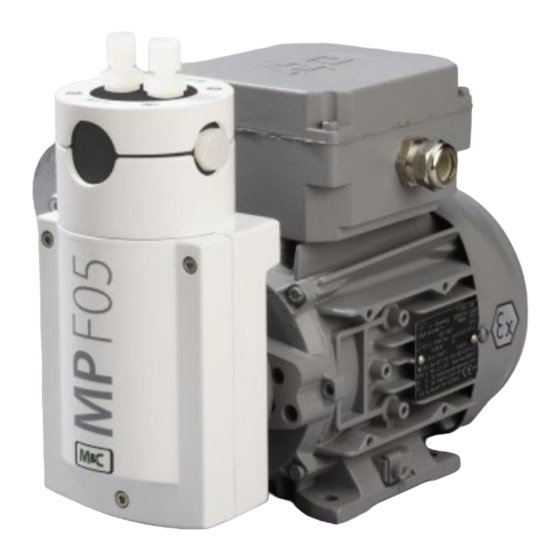
- Page 1 Bellows pump series MP ® MP-F05/EX, MP-F05/R/EX, MP-F10/EX, MP-F10/R/EX (Valid as of Serial No. 21021130) Instruction Manual Version 1.05.04...
- Page 2 Dear customer, Thank you for buying our product. In this manual you will find all necessary information about this M&C product. The information in the manual is fast and easy to find, so you can start using your M&C product right after you have read the manual.
-
Page 3: Table Of Contents
Table of Contents Important product information: new drive motor ..................4 General information ............................. 4 Declaration of conformity ........................... 5 Warranty................................. 5 Warning signs and definitions ..........................6 Correct operation ..............................8 Wrong operation ..............................9 Safety instructions for using the pump in potentially explosive atmospheres ........10 Application ................................10 9.1 MP-F05/R/EX and MP-F10/R/EX with integrated needle valve .................... -
Page 4: Important Product Information: New Drive Motor
Headquarters M&C TechGroup Germany GmbH Rehhecke 79 40885 Ratingen Germany Phone: +49 - 2102 - 935 - 0 E - Mail: info@mc-techgroup.com Website: www.mc-techgroup.com Important product information: new drive motor Our longtime supplier, the company ATB, has stopped the production of our drive motors. For this reason the MP- F/EX pumps will be delivered with a new drive motor from the company ORANGE1 ELECTRIC MOTORS S.p.A. -
Page 5: Declaration Of Conformity
Declaration of conformity CE - Certification The product described in this operating manual complies with the following EU directives: ATEX-Directive The product described in this manual is produced in accordance with the EU directive for devices and protection systems for appropriate use in hazardous areas 2014/34/EU appendix II. Machinery Directive The requirements of the EU directive 2006/42/EC are met. -
Page 6: Warning Signs And Definitions
Warning signs and definitions The ‘Danger’ warning sign indicates that death, serious injury and/or significant ma- terial damage will be the consequence, if the appropriate precautions should not Danger be taken. The ‘Warning’ warning sign indicates that death, serious injury or damage to prop- erty may occur, if the relevant precautionary measures are not observed. - Page 7 Wear protective gloves! Working with chemicals, pointed objects or extremely high temperatures requires wearing protective gloves. Wear safety glasses! Protect your eyes while working with chemicals or pointed objects. Wear safety glasses to avoid getting something in your eyes. Wear protective clothes! Working with chemicals, pointed objects or extremely high temperatures requires wearing protective clothes.
-
Page 8: Correct Operation
Correct operation Follow these fundamental safety precautions during installation, commissioning and operation of the de- vice: • Read this instruction manual before commissioning and operating the product. Make sure to follow all warnings and safety instructions. • Installation and commissioning of electrical devices must be carried out only by qualified skilled personnel in compliance with the current regulations. -
Page 9: Wrong Operation
Wrong operation Please make sure to install and operate the pump for the intended use described in this instruction manual only. Warning The pump can only be operated within the parameters stated in the technical data of chapter ‘10Technical data’ on page 13. Warning The pump is not designed for liquids or particles. -
Page 10: Safety Instructions For Using The Pump In Potentially Explosive Atmospheres
If components downstream from the pump can block or reduce the sample gas flow, appropriate measure, e.g. a pressure valve, needs to be installed to prevent Warning the process pressure from exceeding the maximum permitted pressure value. Safety instructions for using the pump in potentially explosive atmospheres The bellows pump MP-F…/EX is designed to be used in potentially explosive atmospheres of zone 1, and belongs to the equipment category 2G. -
Page 11: Mp-F05/R/Ex And Mp-F10/R/Ex With Integrated Needle Valve
Two different pump capacities are available: • MP-F05/EX pump capacity 5 Nl/min (approx. 320 Nl/h) • MP-F10/EX pump capacity 10 Nl/min (approx. 600 Nl/h) Liter capacity with a counter pressure of ±50 mbar on the vacuum and pressure side. • Option: integrated needle valve to adjust the flow rate in the pump head of the MP F.../R/EX and/or •... -
Page 12: Figure 1 Needle Valve In A Half-Section View With One Quarter Removed
Figure 1 Needle valve in a half-section view with one quarter removed The reliability of the pump is increased by use of a bypass needle valve. This needle valve protects the pump from unnecessary high loads or overload. Figure 2 Pump with bypass needle valve MP-F…/EX | 1.05.04 www.mc-techgroup.com... -
Page 13: Technical Data
Technical data Bellows pump MP-F05/EX MP-F05/R/EX Part No. 05P1100 05P1100a 05P1110 05P1110a Integrated needle valve Voltage 230 V 115 V 230 V 115 V Frequency 50 to 60 Hz Voltage tolerance In accordance with IEC 60034-1 Voltage ±10 % Frequency ±1 % Degree of protection IP 54 - DIN 40050 Capacity max. - Page 14 Bellows pump MP-F10/EX MP-F10/R/EX Part No. 05P1105 05P1105a 05P1115 05P1115a Integrated needle valve Voltage 230 V 115 V 230 V 115 V Frequency 50 to 60 Hz Voltage tolerance In accordance with IEC 60034-1 Voltage ±10 % Frequency ±1 % Degree of protection IP 54 - DIN 40050 Capacity max.
-
Page 15: Pump Capacity
10.1 Pump capacity Figure 3 Pump capacity MP-F.../EX 10.2 Dimensions Figure 4 Dimensions MP-F.../R/EX www.mc-techgroup.com MP-F…/EX | 1.05.03... -
Page 16: Receiving And Storing The Bellows Pump
Receiving and storing the bellows pump 1. Please remove the bellows pump carefully from the packaging. Check the scope of the delivery specified on the delivery note. Please make sure that you have received all items stated on the delivery note. 2. -
Page 17: Installation Instructions
Installation instructions All relevant regulations regarding accident prevention and safety need to be met during installation and operation of the pump. High voltage! Warning Working without disconnecting the power supply may cause an electrical shock. Dis- connect power supply before any assembly, maintenance or repair work. Secure the pump against accidental restart! Protect yourself and others against contact to parts of the pump, e.g. - Page 18 Aggressive condensate possible! Chemical burns caused by aggressive media possible! For general electrical and mechanical work on the pump, wear personal protective equipment (PPE) in accordance with the risk assessment. Moisture in the pump head will destroy the pump. Even though condensation could occur in the rarest of cases, e.g. due to the pres- sure dew point being exceeded or due to a malfunction in the extraction process, the following measures must be taken: •...
-
Page 19: Installation In Potentially Explosive Atmospheres
12.1 Installation in potentially explosive atmospheres In potentially explosive areas (zones) use only pumps, which are in the correspond- ing equipment category, explosive group and temperature class! If the standard configuration is changed by using components or parts not speci- fied and not authorized by M&C, the type examination certificate will no longer be valid. - Page 20 Make sure to pay attention to the current version of the explosion protection regu- lations (EX-RL) regarding the environment of the pump in an explosion protected area (zone): ‘A collection of technical regulations on the prevention of hazards caused by an ex- plosive atmosphere with a collection of examples showing how to classify risk areas into zones’(available in German) For specific cases or if you have any doubt about the correct category of a poten-...
-
Page 21: Mounting The Pump
12.2 Mounting the pump Condensate in the pump head will destroy the pump. Even though condensation could occur in the rarest of cases, e.g. due to the pres- sure dew point being exceeded or due to a malfunction in the extraction process, the following measures must be taken: •... -
Page 22: Rotating The Pump Head
12.3 Rotating the pump head By loosening the four flange screws, the position of the pump head relative to the motor foot can be changed in 90° steps. Proceed as follows: • Please unscrew and remove the three lid screws. •... -
Page 23: Electrical Connections
The following figure shows a pump with a rotated pump head and with a sample gas outlet tubing that is installed with a downward slope to the downstream components. To the downstream components Figure 7 Pump head facing down: install outlet tubing with a downward slope 12.5 Electrical connections Be sure to observe all relevant safety regulations during the electrical installation of the pump. -
Page 24: Motor Protection Circuit Breaker For Motor Ii 2 G Ex Db Flameproof Enclosure
Wrong voltage can destroy the device. When connecting the equipment, please make sure that the supply voltage is identi- cal with the supply voltage stated on the product label. The supply voltage can only deviate max. ±10 %, and the frequency can only deviate in the range of 50 to 60 Hz Warning ±1 % from the value stated on the product label. -
Page 25: Figure 8 Wiring Diagram: 3-Phase Motor Protection Circuit Breaker Connection To 1-Phase Motor
• The protective device must not be set higher than the rated current (rated current I ) of the motor. It must respond within 2 hours at 1.2 times the set current. At 1.05 times the set current, however, it must not respond within 2 hours. -
Page 26: Figure 9 Motor Protection Characteristic, Tripping: 1.2 Times Setting Current, Within 2 Hrs
Figure 9 Motor protection characteristic, tripping: 1.2 times setting current, within 2 hrs. • Install a device to disconnect the pump motor from all poles of the main power supply according to EN 60335-1. • The pump needs to be installed in such a way, that contact to parts carrying live voltage (e.g. electrical connections) is impossible. -
Page 27: Figure 10 Electrical Connection
• To connect the wires to the power supply, the junction box includes a built-in terminal for joining the wires, and a cable fitting with a thread: M20 x pitch: 1.5. The wire clamp has a range of 6 mm to 10 mm [≈ 0.24” to 0.39”]. The maximum size of the wire cross-section is 2.5 mm [≈... -
Page 28: Pneumatic Connections
• Keep the inside of the junction box clean. • Close lid of the junction box. Make sure that the lid does close correctly, and the sealing of the box is still in good condition. 12.7 Pneumatic connections 1. Remove protective plugs from the gas connection threads (thread size G 1/4“). 2. -
Page 29: Start Up
3. Slide the clamp ring with the thicker bulge facing the nut, over the connecting tube. 4. Slide the connecting tube on the support nipple of the fitting. 5. Hand-tighten the nut. The connecting tube is now slip-proof and pressure-tight mounted to the tube connection fitting. -
Page 30: Operating The Pump
The bellows and valve plates are the only consumable parts of the pump. Wear is usually indicated by a drastic reduction in the pneumatic performance. The valve plates need to be replaced, when they are < 1.6 mm [≈ 0.063”] thick. When replacing parts, please have a look at chapter 17 ’Maintenance’. Operating the pump The following ambient conditions are necessary for operating the pump: •... -
Page 31: Disassembly
Disassembly Before switching off the pump (decommissioning), the pump needs to be purged with inert gas or air. Note Aggressive condensate possible! Chemical burns caused by aggressive media possible! For general electrical and mechanical work on the pump, wear personal protective equipment (PPE) in accordance with the risk assessment. -
Page 32: Maintenance
Maintenance It is necessary to schedule maintenance work at least twice a year. The intervals between servicing are dependent on the process and system conditions in your facility. The facility QA/QC plan should address the frequency for maintenance and should be updated based on your operations. Maintenance work on equipment for use in potentially explosive areas needs to com- ply with the corresponding national standards regarding ‘regulations of electrical sys- tems in potentially explosive areas’. - Page 33 Inspect the following pump Action components Check pump for damages of the enclosure and any leakage in regular inter- Pump vals, at least two times per year. Capacitor Check the conditions of the adhesive covers of the vents in regular intervals. Replace capacitor with damaged adhesive cover.
-
Page 34: Replacing The Valve Plates
17.1 Replacing the valve plates If you replace the valve plates, we also recommend to replace the O-rings C at the same time. Note For replacing the valve plates, the sample gas fittings don’t need to be dismounted. To replace the valve plates, proceed as follows: 1. -
Page 35: Replacing The Bellows
2. Install the upper pump head A and then the pressure ring H again. Align both so that the screws fit into the threads in the housing. 3. Check that the bellows are seated correctly. The bellows must be attached to the connecting rod. 4. -
Page 36: Cleaning Instructions
3. Install the upper pump head A and then the pressure ring H again. Align both so that the screws fit into the threads in the housing. 4. Check that the bellows are seated correctly. The bellows must be attached to the connecting rod. 5. -
Page 37: Trouble Shooting
Trouble shooting High voltage! Warning Working without disconnecting the power supply may cause an electrical shock. Dis- connect power supply before any assembly, maintenance or disassembly. Secure the pump against accidental restart. Problem/Indication Possible cause Check/Action Check power supply; Check power cable for No main supply proper connection. -
Page 38: Proper Disposal Of The Device
Proper disposal of the device At the end of the life cycle of our products, it is important to take care of the appropriate disposal of obsolete electrical and non-electrical devices. To help protect our environment, please follow the rules and regulations of your country regarding recycling and waste management. - Page 39 Bellows pump MP-F05/EX, MP-F10/EX, MP-F05/R/EX, MP-F10/R/EX (C) Consumable parts (R) Recommended spare parts (S) Spare parts Recommended amount based on number of years of opera- tion [years] Part No. Description C/R/S 95P0039 Spare screws set for mounting the pump head with 4 x spring washers M4 and 4 x allen socket head screws M4 x 55 95P0040...
-
Page 40: Appendix
Appendix • IBExU Type Examination Certificate in German and English • Eurofins EU-Type Examination Certificate • ORANGE1 ELECTRIC MOTORS Declaration of Conformity Further product documentation can be seen and downloaded from our home page: www.mc-techgroup.com MP-F…/EX | 1.05.04 www.mc-techgroup.com... - Page 41 www.mc-techgroup.com MP-F…/EX | 1.05.03...
- Page 42 MP-F…/EX | 1.05.04 www.mc-techgroup.com...
- Page 43 www.mc-techgroup.com MP-F…/EX | 1.05.03...
- Page 44 MP-F…/EX | 1.05.04 www.mc-techgroup.com...
- Page 45 www.mc-techgroup.com MP-F…/EX | 1.05.03...
- Page 46 MP-F…/EX | 1.05.04 www.mc-techgroup.com...
- Page 47 www.mc-techgroup.com MP-F…/EX | 1.05.03...
- Page 48 MP-F…/EX | 1.05.04 www.mc-techgroup.com...
- Page 49 www.mc-techgroup.com MP-F…/EX | 1.05.03...
- Page 50 MP-F…/EX | 1.05.04 www.mc-techgroup.com...
- Page 51 www.mc-techgroup.com MP-F…/EX | 1.05.03...