M&C MP-F Series Instruction Manual
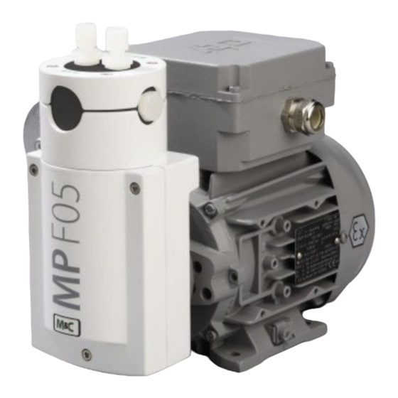
Bellows pump
Hide thumbs
Also See for MP-F Series:
- Instruction manual (30 pages) ,
- Instruction manual (51 pages) ,
- Instruction manual (35 pages)

Related Manuals for M&C MP-F Series


Summary of Contents for M&C MP-F Series
- Page 1 ® Bellows pump series MP MP-F05/EX, MP-F05/R/EX, MP-F10/EX, MP-F10/R/EX Instruction Manual Version 1.04.00...
- Page 2 Dear customer, Thank you for buying our product. In this manual you will find all necessary information about this M&C product. The information in the manual is fast and easy to find, so you can start using your M&C product right after you have read the manual.
-
Page 3: Table Of Contents
Table of Contents General information ........................4 Declaration of conformity ......................4 Warranty ............................5 Warning signs and definitions ....................5 Correct operation ........................7 Wrong operation ......................... 8 Safety instructions for using the pump in potentially explosive atmospheres ...... 9 Application .......................... -
Page 4: General Information
Headquarters M&C TechGroup Germany GmbH Rehhecke 79 40885 Ratingen Germany Phone: +49 - 2102 - 935 - 0 E - mail: info@mc-techgroup.com Website: www.mc-techgroup.com General information The product described in this instruction manual has been built and tested in our production facility. All M&C products are packed to be shipped safely. -
Page 5: Warranty
Warranty In case of a device failure, please contact immediately M&C or your M&C authorized distributor. We have a warranty period of 12 months from the delivery date. The warranty covers only appropriately used products and does not cover the consumable parts. Please find the complete warranty conditions in our terms and conditions. - Page 6 High voltages! Protect yourself and others against damages which might be caused by high voltages. Toxic! Acute toxicity (oral, dermal, inhalation)! Toxic when in contact with skin, swollowed or inhaled. Corrosive! These substances destroy living tissue and equipment upon contact. Do not breathe vapors;...
-
Page 7: Correct Operation
Correct operation Follow these fundamental safety precautions during installation, commissioning and operation of the device: • Read this instruction manual before commissioning and operating the product. Make sure to follow all warnings and safety instructions. • Installation and commissioning of electrical devices must be carried out only by qualified skilled personnel in compliance with the current regulations. -
Page 8: Wrong Operation
Wrong operation Please make sure to install and operate the pump for the in- tended use described in this instruction manual only. Warning The pump can only be operated within the parameters stated in the technical data of chapter ‘9Technical data’ on page 11. Warning The pump is not designed for liquids or particles. -
Page 9: Safety Instructions For Using The Pump In Potentially Explosive Atmospheres
If components downstream from the pump can block or reduce the sample gas flow, appropriate measure, e.g. a pressure valve, needs to be installed to prevent the process pressure Warning from exceeding the maximum permitted pressure value. Safety instructions for using the pump in potentially explosive atmospheres The bellows pump MP-F…/EX is designed to be used in potentially explosive atmospheres of zone 1, and belongs to the equipment category 2G. -
Page 10: Mp-F05/R/Ex And Mp-F10/R/Ex With Integrated Needle Valve
MP-F05/R/EX and MP-F10/R/EX with integrated needle valve To ensure that the needle valve works properly, the output of the pump needs to be operated with at least 0.1 bar counter pressure. To adjust the pump capacity, a needle valve used as an internal pump bypass is integrated into the pump head. -
Page 11: Technical Data
Technical data Bellows pump MP-F05/EX MP-F05/EX MP-F10/EX MP-F10/EX Part no. 05 P 1100 05 P 1100a 05 P 1105 05 P 1105a Part no. with needle valve 05 P 1110 05 P 1110a 05 P 1115 05 P 1115a MP-F…/R/EX Voltage 230 V;... -
Page 12: Pump Capacity
Pump capacity Figure 3 Pump capacity MP-F.../EX Dimensions Figure 4 Dimensions MP-F.../R/EX MP-F…/EX | 1.04.00 www.mc-techgroup.com... -
Page 13: Receiving And Storing The Bellows Pump
Receiving and storing the bellows pump • Please remove the bellows pump carefully from the packaging. Check the scope of the delivery specified on the delivery note. Please make sure that you have received all items stated on the delivery note. •... -
Page 14: Installation Instructions
Installation instructions All relevant regulations regarding accident prevention and safety need to be met during installation and operation of the pump. High voltage! Warning Working without disconnecting the power supply may cause an elec- trical shock. Disconnect power supply before any assembly, mainte- nance or repair work. - Page 15 Aggressive condensate possible! Chemical burns caused by aggressive media possible! For general electrical and mechanical work on the pump, wear per- sonal protective equipment (PPE) in accordance with the risk assess- ment. Condensate accumulated inside the pump head destroys the pump. Even if condensate might occur only on very rare occasions, the Warning pump head needs to be rotated 180°...
-
Page 16: Installation In Potentially Explosive Atmospheres
11.1 Installation in potentially explosive atmospheres In potentially explosive areas (zones) use only pumps, which are in the corresponding equipment category, explosive group and temperature class! If the standard configuration is changed by using components or parts not specified and not authorized by M&C, the type examination certifi- cate will no longer be valid. - Page 17 Make sure to pay attention to the current version of the explosion pro- tection regulations (EX-RL) regarding the environment of the pump in an explosion protected area (zone): ‘A collection of technical regulations on the prevention of hazards caused by an explosive atmosphere with a collection of examples showing how to classify risk areas into zones’(available in German) For specific cases or if you have any doubt about the correct category of a potentially explosive zone, please inform and seek advice from...
-
Page 18: Mounting The Pump
11.2 Mounting the pump The mounting site needs to comply with the following requirements: • Ambient temperature range during operation: +10 °C to +50 °C / 0 °C to +50 °C for dry sample gas (+50 °F to + 122 °F / +32 °F to + 122 °F for dry sample gas) •... -
Page 19: Rotating The Pump Head
11.3 Rotating the pump head Condensate accumulated inside the pump head destroys the pump. Even if condensate might occur only on very rare occasions, the pump Warning head needs to be rotated 180° facing downwards. By loosening the four flange screws, the position of the pump head relative to the motor foot can be changed in 90°... -
Page 20: Electrical Connections
11.4 Electrical connections Be sure to observe all relevant safety regulations during the electrical installation of the pump. Before connecting the pump, the electrical supply must be disconnected from the power supply. Wrong voltage can destroy the device. When connecting the equipment, please make sure that the supply volt- age is identical with the supply voltage stated on the product label. -
Page 21: Figure 7 Wiring Diagram: 3-Phase Motor Protection Circuit Breaker Connection To 1-Phase Motor
The tripping time of the overcurrent protection device with current-dependent delayed tripping cannot be higher than the temperature rise time of the motor (T ). You will find the tripping time of the motor protection circuit breaker in the time/current characteristic curve of Figure 8. The time/current charac- teristic curve shows the tripping time T versus the ratio of the start current I to the rated operational... -
Page 22: Figure 8 Tripping Characteristic: Heating Time T Versus I
Figure 8 Tripping characteristic: heating time t versus I • Install a device to disconnect the pump motor from all poles of the main power supply according to EN 60335-1. • The pump needs to be installed in such a way, that contact to parts carrying live voltage (e.g. electrical connections) is impossible. -
Page 23: Figure 9 Electrical Wiring
The wire clamp has a range of 6 mm to 10 mm (0.24” to 0.39”). The maximum size of the wire cross-section is 2.5 mm (0.0039 in • To connect the single wires, please refer to Figure 9. Figure 9 Electrical wiring •... -
Page 24: Pneumatic Connections
• Keep the inside of the junction box clean. • Close lid of the junction box. Make sure that the lid does close correctly, and the sealing of the box is still in good condition. 11.6 Pneumatic connections • Remove protective plugs from the gas connection threads (thread size G1/4“). •... -
Page 25: Start Up
Because of compression of sample gases, it is possible that condensate builds up in the pressure line. This pressure must be reduced. For example, reduce the pressure with a valve in the pressure line upstream Note of the pump or with the integrated needle valve. Start up Before commissioning, be sure to comply with all applicable facility- and process-specific safety measures. -
Page 26: Operating The Pump
Operating the pump The following ambient conditions are necessary for operating the pump: • Ambient temperature range during operation: +10 to +50 °C / 0 to +50 °C for dry sample gas (+50 °F to + 122 °F / +32 °F to + 122 °F for dry sample gas) •... -
Page 27: Disassembly
Disassembly Before switching off the pump (decommissioning), the pump needs to be purged with inert gas or air. Note Aggressive condensate possible! Chemical burns caused by aggressive media possible! For general electrical and mechanical work on the pump, wear personal protective equipment (PPE) in accordance with the risk assessment. -
Page 28: Maintenance
Maintenance It is necessary to schedule maintenance work at least twice a year. The intervals between servicing are dependent on the process and system conditions in your facility. The facility QA/QC plan should address the frequency for maintenance and should be updated based on your operations. - Page 29 Inspect the following Action pump components Pump Check pump for damages of the enclosure and any leakage in regu- lar intervals, at least two times per year. Capacitor Check the conditions of the adhesive covers of the vents in regular intervals.
-
Page 30: Replacing The Valve Plates
16.1 Replacing the valve plates If you replace the valve plates, we also recommend to replace the O- rings C at the same time. Note For replacing the valve plates, the sample gas fittings don’t need to be dismounted. To replace the valve plates, proceed as follows: 1. -
Page 31: Replacing The Bellows
2. Install the upper pump head A and then the pressure ring H again. Align both so that the screws fit into the threads in the housing. 3. Check that the bellows are seated correctly. The bellows must be attached to the connecting rod. 4. -
Page 32: Cleaning Instructions
3. Install the upper pump head A and then the pressure ring H again. Align both so that the screws fit into the threads in the housing. 4. Check that the bellows are seated correctly. The bellows must be attached to the connecting rod. 5. -
Page 33: Trouble Shooting
Trouble shooting High voltage! Working without disconnecting the power supply may cause an electrical Warning shock. Disconnect power supply before any assembly, maintenance or disassembly. Secure the pump against accidental restart. Problem/Indication Possible cause Check/Action No main supply Check power supply; Check power cable for proper connection. -
Page 34: Spare Parts List
Spare parts list The replacement interval for spare parts and consumables depends on the specific operating condition of the bellows pump. The quantities recommended in the following table are based on experience. Your replacement intervals will be based on your operating conditions. Bellows pump MP-F05/EX, MP-F10/EX, MP-F05/R/EX, MP-F10/R/EX (C) Consumable parts (R) Recommended spare parts... -
Page 35: Appendix
PVDF male connectors with G-thread (ISO 1010031) C) Consumable parts (R) Recommended spare parts (S) Spare parts Recommended amount based on number of years of operation [years] Part No. Description C/R/S 05 V 1060 Straight male connector DN 4/6-G1/4”, material: PVDF 05 V 1065 Straight male connector DN 6/8-G1/4”, material: PVDF... - Page 36 MP-F…/EX | 1.04.00 www.mc-techgroup.com...
- Page 37 www.mc-techgroup.com MP-F…/EX | 1.04.00...
- Page 38 MP-F…/EX | 1.04.00 www.mc-techgroup.com...
- Page 39 www.mc-techgroup.com MP-F…/EX | 1.04.00...
- Page 40 MP-F…/EX | 1.04.00 www.mc-techgroup.com...
- Page 41 www.mc-techgroup.com MP-F…/EX | 1.04.00...
- Page 42 MP-F…/EX | 1.04.00 www.mc-techgroup.com...
- Page 43 www.mc-techgroup.com MP-F…/EX | 1.04.00...
- Page 44 MP-F…/EX | 1.04.00 www.mc-techgroup.com...
- Page 45 www.mc-techgroup.com MP-F…/EX | 1.04.00...
- Page 46 MP-F…/EX | 1.04.00 www.mc-techgroup.com...
- Page 47 www.mc-techgroup.com MP-F…/EX | 1.04.00...
- Page 48 MP-F…/EX | 1.04.00 www.mc-techgroup.com...
- Page 49 www.mc-techgroup.com MP-F…/EX | 1.04.00...
- Page 50 MP-F…/EX | 1.04.00 www.mc-techgroup.com...
- Page 51 www.mc-techgroup.com MP-F…/EX | 1.04.00...
Need help?
Do you have a question about the MP-F Series and is the answer not in the manual?
Questions and answers