Table of Contents
Advertisement
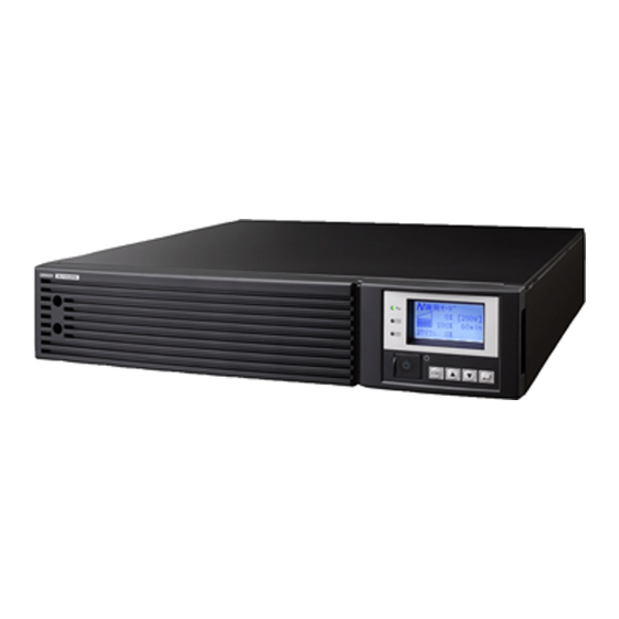
Uninterruptible Power Supply (UPS/200-240V model)
BU1002RW
Instruction Manual
• This manual provides important safety-related information. Thoroughly read and understand
this manual before installing and using the product.
• Keep this manual in a convenient location so that you can refer to it whenever necessary.
• The contents of this manual are subject to change without notice.
中文使用说明书请参照"10. Notes of Chinese" 。
使用说明书
ESC
Advertisement
Table of Contents

Related Manuals for Omron BU1002RW


Summary of Contents for Omron BU1002RW
- Page 1 Uninterruptible Power Supply (UPS/200-240V model) BU1002RW Instruction Manual 使用说明书 • This manual provides important safety-related information. Thoroughly read and understand this manual before installing and using the product. • Keep this manual in a convenient location so that you can refer to it whenever necessary.
-
Page 2: Introduction
Introduction Features of this product Thank you for purchasing Omron's Uninterruptible Power Supply (UPS). ● The UPS protects computers and other devices from power failures, voltage variations, in- stantaneous voltage drops, and surge voltage such as that caused by lightning (a phenom- enon in which extraordinary high voltage occurs instantaneously). -
Page 3: Important Safety Instruction
IMPORTANT SAFETY INSTRUCTION 1. SAVE THESE INSTRUCTIONS. This manual contains important instructions for BU1002RW that should be followed when using the UPS and batteries. 2. SYMBOL This symbol indicates earth ground. This symbol indicates turning on UPS. This symbol indicates turning off UPS. -
Page 4: Preparation For Operation
Procedure from installation to operation Read “Safety precautions” Start Page v Remove the product from the package and check the contents Page 1 Installation/connection Perform installation and connection Page 5 Are you Read “Using the UPS using UPS monitoring monitoring software and software or contact contact signal”... -
Page 5: Table Of Contents
Table of Contents Table of Contents Introduction ............................i IMPORTANT SAFETY INSTRUCTION ....................ii Safety precautions ..........................v 1. Preparation .............................1 1-1 Unpacking the product ........................1 1-2 Checking the contents ......................... 1 1-3 Name of each part ..........................2 1-4 Explanation of symbols used on unit.................... -
Page 6: Safety Precautions
Important information for safe operation is described. Safety precautions Be sure to read it before installation and start of use. ● The safety symbols and their meaning used in this manual are as follows: Warning Misuse may cause death or serious injury. Caution Misuse may cause injury or property damage. - Page 7 Safety precautions Caution (for installation and connection) When an abnormality (unusual sound or smell) occurs, turn OFF the external breaker installed on the input side. ● When performing maintenance on the connected devices, follow the above instructions to ensure safety. Do not connect devices such as dryers, some solenoid valves, etc., which have a half-wave rectifier that allows only half-cycle AC power to flow through.
- Page 8 Caution (for installation and connection) Do not exceed the ranges specified for environmental conditions during use/storage. Do not install or store the unit in the places listed below. ● Do not store in places where the humidity is lower than 10% or higher than 90%. ●...
- Page 9 Safety precautions Caution (for use) Do not allow the unit to come in contact with water. If you drop the unit, stop using it. ● Doing so may cause an electric shock or a fire. ● If the unit becomes wet or is dropped, immediately stop using it, disconnect the AC input cable from commercial power and have the unit inspected and repaired.
- Page 10 Use a specified battery for replacement. ● Not doing so may cause a fire. ● Replacement battery pack for BU1002RW: BUB1002RW Do not replace the battery in a place where there is flammable gas. ● Spark may occur when connecting the battery, which may cause an explosion or fire. If fluid (dilute sulfuric acid) leaks from the battery, do not touch the fluid.
- Page 11 Safety precautions Notes When moving the unit from a cold place to a warm place, leave it for several hours before using it. ● If the unit is promptly turned ON after being moved to a warmer place, condensation may form inside the unit and cause it to fail.
- Page 12 Notes Check system operation beforehand if the unit is used in combination with a device whose power supply voltage and frequency fluctuate widely, such as a generator. ● If the generator’s output voltage/frequency falls out of the input voltage/frequency range, the unit will enter Battery Mode.
-
Page 13: Preparation
Open the package box and take out the UPS and accessories. Checking the contents Check whether all the package contents are included and there is no damage found on their appearance. If you should notice defects or anything wrong, contact us; OMRON Electronic Systems & Equipments Customer Support Center. Item... -
Page 14: Name Of Each Part
1002 Name of each part This section describes the name of each part of the UPS. For information on the function of each part, refer to "2. Installation and connection" on page 5 and "3. Operation" on page 24 that provides the details. Front view <Air vent>... -
Page 15: Rear View
.Preparation Rear view A. Option slot F. AC input overcurrent protection switch B. Remote ON/OFF port G. Input surge protection GND C. RS-232C port H. Grounding terminal (M4 screw) D. Contact signal port I. AC input terminal block E. Cooling fan J. -
Page 16: Explanation Of Symbols Used On Unit
1002 Explanation of symbols used on unit Symbol Description Start the UPS. Stop the UPS. Suspend a beep. UPS output power enabled, supplied by operating on line mode, battery mode. Bypass output “ON”. UPS output power enabled, supplied by operating on battery mode. Batteries at end of useful life, necessary to replace the batteries. -
Page 17: Installation And Connection
Installation and connection Precautions and notes on installation and connection Caution (for installation and connection) Carry the unit considering its weight and balance, and place it on a stable and robust base. Dropping or toppling the unit may cause injury. ●... - Page 18 1002 Caution (for installation and connection) When in use, make sure the terminal block cover is attached. Do not turn ON the power switch when it is detached. ● Voltage is applied to the output terminal block when the power switch is ON, which can result in electric shock.
-
Page 19: Battery Mode
.Installation and connection Caution (for installation and connection) supply. ● When the unit’s power switch is turned ON and an error occurs with the connected device, by- pass operation is performed and commercial power supply is supplied as is to the connected devices. - Page 20 1002 Notes Before performing a withstand voltage test or insulation resistance test, make sure to remove the input surge protection GND screw from the back of the unit. When in use, make sure the input surge protection GND screw is securely fastened.
-
Page 21: Installation
.Installation and connection Installation The UPS permits the following installing methods. Choose the one best suited for the environment. 2-2-1. Rackmount installation 2-2-2. Stationary installation Horizontal ● Upright intatllation ● Do not use this unit in any position other than the “correct positions” indicated in the illustration below. Note Before installing this device, make a record of the serial number of this device. - Page 22 Without the support angles, the front clamp alone cannot support the weight of the UPS. ● The mass of each unit: BU1002RW: Approx. 18kg In a case where the UPS is to be mounted on a rack, place it on the lower part of the rack.
- Page 23 .Installation and connection (2) Adjust the length of support angles to suit the server rack, and then securely tighten the screws that were half-tightened in step 1. ② (3) For EIA standard-compliant installation, use the 8 included EIA rack fixing nuts (M5) and 8 EIA/JIS rack fixing screws (M5) to securely fasten the front (the side displaying “L” or “R”) and the back of the support angles to the server rack.
- Page 24 1002 (5) Place the UPS on the support angles and push it completely into the rack ⑤ , and use the 2 included EIA/JIS rack fixing screws (M5) to securely fasten the ear brackets to the server rack. ⑥ Push completely in Use the unit fixing screws to fasten Always use the support angles.
- Page 25 .Installation and connection 2-2-2. Stationary installation Perform installation only as shown in the diagrams below. ● H orizontal installation Attach the included rubber feet for horizontal installation with the included screw rivets and position the unit horizontally. For stationary horizontal installation, make sure that this product does not slide or fall. ● U pright installation (1) Upright installation Use the upright stands (2) and M3 flat-head screws (6) included with the product.
-
Page 26: Connecting The Equipment
1002 Connecting the equipment Caution Do not connect devices with rated voltage of other than 200/208/220/230/ 240/100VAC. ● The rated output voltage of this device is 200/208/220/230/240/100VAC. ● Overcurrent may damage the connected devices. 2-3-1. Connecting a device to the power supply output (AC output terminal block) Caution The output wiring work should be performed by a service person. - Page 27 .Installation and connection Crimp the ring type crimp terminal that is UL/CSA listed to the ground wire, and tighten the ground terminal screw. (See figure2) Ring type crimp terminal (M4) ex. AWG14:V2-M4(JST) , AWG12:V5.5-4(JST) If you cannot get specified ring type crimp terminals, please contact our Electronic Systems & Equipments customer support center. Figure 1 Fasten Torque 22kgf•cm 38kgf•cm Figure 2...
- Page 28 1002 (2) Attach the terminal block cover (with cable clamp) to the unit. Insert the upper part of the terminal block cover into the slit of the unit, and tighten it with two of the included M3 screws. Tighten the cable clamp dial to stabilize the wire. 2-3-2.
-
Page 29: Connecting The Ac Input
(with Type II certification or higher). ● To use the BU1002RW with up to 1000VA/800W, a wiring capacity of 7A or required. Make sure to properly match the AC input terminal. Turn off the external breaker when performing work on the unit's AC input terminals. Be sure to attach the terminal block cover. - Page 30 1002 (Example of connection) Power supply 200 VAC External breaker Load Isolator switch with 250V/20A. (double pole) Breaker ● The unit was charged before shipment, but it may have self-discharged during shipment, resulting in a reduced backup time. We recommend charging the unit before use. ●...
-
Page 31: Checking The Operation
.Installation and connection Checking the operation When you finish connecting the unit, confirm that the backup operation works properly. Check that the Battery Mode is performed normally according to the following procedure. (In this operation check, the effects of a power failure are reproduced by disconnecting the AC input from the commercial power.) (1) Starting the UPS and setting the LCD menu language. - Page 32 1002 (5) Under this condition, check the the unit's LCD and beep sound. Are they in the same status as shown below? Status indicator Beep None Power supply output Outputs power (connected devices are powered) If the same as the one shown above: → The operation is normal. Proceed to (6). If not the same as the one shown above: → The operation is abnormal. One of the cases described in "4.
-
Page 33: Charging The Battery
.Installation and connection (8) Reconnect the AC input to the commercial power source. Turn on the external breaker. The status indicator returns to its normal state and the beeping sound stops. (The status is as shown below.) Status indicator Description Power switch “ON”... -
Page 34: Operation
Operation Precautions and notes for operation Take notice of following items during operation. Caution (for use) Do not allow the unit to come in contact with water. Do not drop the unit. ● Doing so may cause an electric shock or a fire. ● If the unit becomes wet, immediately stop using it, disconnect the AC input cable from commer- cial power and have the unit inspected and repaired. - Page 35 .Operation Notes Before stopping the commercial power to the unit, turn OFF the power switch of the unit. ● The unit enters Battery Mode when commercial power is stopped. If you frequently use the unit in Battery Mode, the battery life may be significantly shortened. Take measures for handling unforeseen accidents, such as data backup and system redundancy.
-
Page 36: Start And Stop Procedures And Basic Operation
1002 Start and stop procedures and basic operation The UPS status indicators and UPS setting change menu are displayed on the control display panel on the front of the unit. UPS status indicators (status screen) ● Status indicator Upper text Load level Output setting Battery level... - Page 37 .Operation When the unit is connected to a commercial power source with the power ● switch OFF and commercial power is supplied to it • The status indicator displays " ". • Power output is stopped. • The battery automatically starts recharging. •...
- Page 38 1002 Operation after a power failure ● • If a power failure or abnormal input power supply occurs, the UPS automatically switches to Battery Mode, continuing power output from the Power Supply Output terminal block supplied from the battery. • The LCD and the beeper’s intermittent sounds alert the user. “Local Settings”...
-
Page 39: Interpreting Beeps And Displays
Load/battery level meter ● The load level meter displays the power consumption of the connected devices as a percentage. BU1002RW: Displayed in 10 levels, with 100% indicating 1000VA/800W. The battery level meter displays the remaining battery level as a percentage. -
Page 40: Ups Functions
UPS functions Suspending a beep When the beep is sounding, you can suspend it by pressing and holding the beep ESC switch for 0.5 seconds or longer. Self-diagnosis test This test performs a failure diagnosis on the unit and performs a test to check for battery deterioration. Use the procedure below to check whether a circuit failure has occurred inside the unit and whether battery replacement is required. -
Page 41: Battery Life Counter Function
. UPS functions Battery life counter function This function notifies you with LCD and beep sound when the battery needs to be replaced. The bat- tery life counter operates while commercial power is supplied after shipment. (When the ambient temperature of the battery is higher than 25°C, the value of the counter will be incremented at a faster pace.) When the battery needs to be replaced, the battery replacement lamp will light up and beep will sound. - Page 42 1002 Menu Description Note Settings Local Settings Language Set the language to be displayed on the LCD. LCD Setting Change the contrast of the LCD. LCD Auto off Set the amount of time after which the LCD turns off automatically. LCD Test Check that the LCD and LEDs light up.
- Page 43 . UPS functions Menu Description Note Identification Type Display the names of the UPS and battery pack. Serial Number Display the serial number of the UPS. Firmware Ver. Display the firmware version of the UPS. Memorandum You can record information of 20 alphanumeric characters. Fault Log Display up to 10 fault log records (time of occurrence and details of each failure).
-
Page 44: Measuring The Backup Time
Measuring the backup time How to measure backup time The backup time you measure for the first time after purchase is the “initial value of the backup time.” You can precisely judge the deterioration condition of the battery if you measure the “initial value of the backup time” in advance at the time of a battery check. (1) Connect to commercial power and charge the battery for 8 hours (Charging time is extended 24 hours per unit, if additional battery unit is connected). - Page 45 . Measuring the backup time Backup time (25°C, initial value) BU1002RW Connection capacity (W) Backup time table Time unit: (Minutes) Connection capacity (Watt) Type 100W 200W 300W 400W 500W 600W 700W 800W BU1002RW * These backup times are for reference only. Times may vary according to battery life and external environmental...
-
Page 46: Maintenance And Inspection
Maintenance and Inspection Caution (for maintenance) When maintaining the connected equipment, turn OFF the unit’s power switch to stop the output, and stop the supply of commercial power. ● Even if commercial power to the UPS is stopped while it is in operation, the power output of this unit does not stop and power is supplied from the terminal. -
Page 47: Replacing The Battery
Use a specified battery for replacement. ● Not doing so may cause a fire. ● Replacement battery pack for BU1002RW: BUB1002RW Do not replace the battery in a place where there is flammable gas. ● Spark may occur when connecting the battery, which may cause an explosion or fire. If fluid (dilute sulfuric acid) leaks from the battery, do not touch the fluid. - Page 48 1002 ● A battery can present a risk of electrical shock and high short circuit current.The following pre- cautions should be observed when working on batteries: 1) Remove watches, rings, or other metal objects from the hands. 2) Use tools with insulated handles. 3) Wear rubber gloves and boots.
- Page 49 Pull here to remove the battery pack Battery connector Insert the new battery on the straight into the unit as far as it will go. ① ● Replacement battery pack For BU1002RW: Model BUB1002RW Securely connect the connectors. ② ① ② Description Specification Nominal voltage of total battery strings 36 VDC (12 V×3 PCS)
- Page 50 1002 Attach the plate cover. Insert the tab on the left side of the plate cover into the hole in the UPS body ① , and push the plate cover toward the body. Securely tighten the 2 screws that were removed from the right side of the plate cover. ② As shown in the figure, run the cable to the right side...
-
Page 51: Cleaning
. Maintenance and Inspection Cleaning 1. Cleaning the UPS Moisten a soft cloth with water or detergent, squeeze it tightly, and wipe the product lightly. Do not use chemicals such as thinner and benzene. (They cause deformation or discoloration.) 2. Removing dust from the input terminal block, and output terminal block of the UPS Stop all the connected devices and the UPS and disconnect the AC input from the commercial power. -
Page 52: Using The Ups Monitoring Software And Contact Signal
PowerAct Pro 4.x (Slave Agent) (Note1) SC20G → See 8-1 Note 1: The most recent version can be downloaded from our homepage (http://www.omron.co.jp/ese/ups/download/category_u.htm). Note 2: Files cannot be automatically saved. Note 3: The UPS automatically stops once the battery is depleted. - Page 53 . Using the UPS monitoring software and contact signal • UPS monitoring software function list ● Supported ▲ Limited ━ Unsupported Network SNMP management management General applications applications applications Software title (Simple functions, standalone) (Advanced functions, (Advanced functions, network support) network support) Function Simple...
-
Page 54: When Using The Included Ups Monitoring Software To Perform Auto Shutdown
The included “Simple Shutdown Software” allows you to automatically shut down the PC when a power failure occurs. For more information, refer to the manual in the CD-ROM. 1. Connect the UPS to a computer. Cable: Included connection cable (RS-232C) <RS-232C> BU1002RW RS-232C端子 Connect to に接続する RS-232C... - Page 55 . Using the UPS monitoring software and contact signal * When connecting 2 or more computers to the UPS (Only when using PowerAct Pro) Power cable Power cable LAN connection PC server 3 Power cable Network PC server 2 Power cable Switching hub PC server 1 Remote connection...
-
Page 56: When Performing Auto-Save Functions Using The Ups Service In Windows Server 2003/Xp/2000 + Ups Service Driver
1002 When performing auto-save functions using the UPS service in Windows Server 2003/XP + UPS service driver When using the included "UPS service driver", the OS standard UPS service in Windows Server 2003/ XP can be used. When there is a power failure the computer can be shut down. 1. -
Page 57: Contact Signal
. Using the UPS monitoring software and contact signal Contact signal Contact signals are included as standard for the unit. Contact Signal You can develop your unique system based on the following specifications to automate the process at a power failure. You can perform power-failure processing by allowing the system to detect the backup signal and also perform system shutdown processing by allowing the system to detect the Low battery level signal. - Page 58 1002 7-4-3. Contact signal I/O connector (female DSUB9P) Pin assignment Pin number Item Battery LOW signal output (BL) Trouble signal output (TR) Backup stop signal input (BS) 5 4 3 2 1 9 8 7 6 COMMON (COM) Front view Remote ON/OFF input (-) Screw size: inch screw Remote ON/OFF input (+)
- Page 59 . Using the UPS monitoring software and contact signal 7-4-6. Contact Signal circuit inside the UPS +5 VDC +5 VDC +5 VDC 1 kΩ 470Ω 470Ω Remote ON/OFF (+) 3 to 7 kΩ Remote ON/OFF (-) 7-4-7. Example of the use of the Contact Signal circuit ●...
- Page 60 1002 7-4-8. Precautions and notes for the use of the Contact Signal Notes ● When connecting a device such as a relay that generates counter electromotive force to the signal output circuit, connect diodes that prevent counter electromotive force to both ends of the relay.
-
Page 61: Using Snmp/Web Card
Using SNMP/Web card Caution Adding SNMP/Web card should be performed by a service person. Adding SNMP/Web card SNMP/Web card can be loaded into the option slot on the back of the unit. • SNMP/Web card (model number: SC20G), sold separately (1) Turn OFF the power switch and disconnect the AC input. -
Page 62: Snmp/Web Card Outline
Number of controllable computers 32 max. (including slave UPS when coordinated shutdown is enabled) UPSMIB (RFC1628) Support MIB OMRON MIB 0 to 40°C/25 to 85% Operating temperature/humidity * Note that the range of the operating temperature/humidity differs from that of BU-RW. -
Page 63: Troubleshooting
2. AC input overcurrent protection is activated and power is cut. (For mercial power and the power BU1002RW, the black button has popped up.) switch is turned ON. • If the black INPUT PROTECTION button pops up, there are too many con- nected devices or there was a short-circuit with the connected devices. -
Page 64: Notes Of Chinese
Notes of Chinese 使用注意事项 不间断电源(UPS) 承蒙惠购本公司的不间断电源 ( 以下简称 UPS),谨致谢意。 使用前,请务必仔细阅读本文的“使用注意事项” 。 1. 前言 UPS 的用途 ● 本装置的设计和生产目的是为了用于计算机等 FA、OA 设备。 请勿用于要求高度可靠性或安全性的下述用途。 · 直接关系到人类生命安全的医疗设备 · 可能导致人体受伤的用途。 (直接影响飞机、船舶、铁路等运行、运转、控制等用途) · 车载、船舶等可能随时发生振动的用途。 · 发生故障后可能对社会、公共财物造成重大损失或影响的用途。 (主要的电子计算机系统、中枢通信设备、公共交通系统等) · 相当于上述用途的设备 ● 关系到人类生命安全、可能对维护公共职能带来重大影响的装置等在实现系统多元化、紧急备用 发电设备等的应用维护及管理方面尤其需要慎重。 ● 使用时请务必严守使用说明书中所记载的使用条件、环境要求等。 ● 尤其在要求高度可靠性的重要系统等上使用时, 请务必向 欧姆龙自动化 (中国) 有限公司进行咨询。 ●... - Page 65 . Notes of Chinese 2. 安全注意事项 为了确保安全使用,以下将就相关重要事项进行说明。 设置或开始使用前请务必仔细阅读。 ● 本使用说明书中的相关安全符号及其含义如下所述。 危 险 表示操作失误可能会导致人员伤亡的内容。 注 意 表示操作失误可能会致残、导致物质损失的内容。 ※ 所谓物质损失,是指房屋、家产以及家畜、宠物相关的连带损失。 : 表示禁止(不可发生的行为) 。例如 表示禁止擅自拆卸。 : 表示强制(必须的行为) 。例如 表示必须进行接地连接。 此外,即使是注意事项中所记载的内容,也可能根据不同的状况而导致严重后果。 这里记述的均为重要内容,请务必严守。 危 险 ( 产品用途 ) 不得将本装置用于下述要求高度可靠性或安全性的用途。 ※ 本装置的设计和生产目的是为了用于计算机等 FA、OA 设备。 ·直接关系到人类生命安全的医疗设备或系统。 ·直接关系到人身安全的相关用途。 (例如 : 车辆等的运行、运转、控制等) ·发生故障后可能对社会、公共财物造成重大损失的用途。...
- Page 66 1002 注 意 ( 设置·连接时 ) 本装置的“AC 输入”插头必须连接至符合产品规格的额定输入电压、 频率 50/60Hz 的电源插座。 ● 如果连接至不同电压、频率的电源插座,则可能引起火灾。 ● 可能导致本装置发生故障。 发现异常(异常声响、异味)时,应关闭“电源”开关停止输出,然后从 电源插座上拔掉“AC 输入”插头。 “AC 输入”插头应设置为可从电源插座上随时拔去的状态。 ● 为了确保安全,连接设备维修保养时等也应按上述标准执行。 不得连接烘干机、部分电磁阀等电流只在交流电源半周期内流动的半波整 流设备。 ● 可能因过电流而导致不间断电源发生故障。 应连接至电流容量在产品规格的最大电流以上的电源插座。 ● 电源配线可能会发热。 ● 连接了最大输出容量的设备时所流动的电流值请参照使用说明书。 应正确进行接地连接(接地) 。 ● 请在确认电源插座的插头形状后,再将本装置的“AC 输入”插头直接插入插座。 若未执行接地连接,则可能因故障或漏电而导致触电事故的发生。 ● 需要拆除接地连接 (接地) 时, 请务必将 “AC 输入” 插头从电源插座上拔掉后再执行。 不得擅自拆卸、维修、改造。...
- Page 67 . Notes of Chinese 注 意 ( 设置·连接时 ) 不得连接超出本装置输出容量的设备。 可通过电源板等增设连接设备,但这种情况下不得连接超出电源板等电流 容量的设备。 ● 本装置检测到过载(超负荷) ,停止输出。 ● 电源板的配线发热,可能导致火灾。 不得在夹住或捆住电缆的状态下使用。 ● 可能因电缆损伤或发热而发生触电、火灾的危险。 ● 若电缆上发现伤痕,请立即停止本装置的使用,并委托相关单位进行维修。 维修事宜请向 欧姆龙自动化(中国)有限公司 客户服务中心维修部 咨询。 同一捆包的所有附件仅限本装置使用。请勿在其他设备上使用。 ● 为了确保设备的安全使用,请务必遵守。 吸排气口不得堵塞。 ● 内部温度上升可能导致本装置发生故障、电池老化。 ● 请设置于前面距离墙面5cm以上,背面距离墙面10cm以上的场所。 不得将变压器、绝缘变压器等连接至输出侧。 ● 可能因过电流而导致不间断电源(UPS)发生故障、或运转异常。 ● 即使连接至输入侧,也依然可能导致不间断电源(UPS)发生故障、 或运转异常。请务必事先检查运转状态后再开始使用。 不得连接无法通过商用电源运转的设备。...
- Page 68 1002 注 意 ( 使用时 ) 不得沾湿、浇水。 ● 可能会导致触电、火灾。 ● 万一沾水时,请立即停止本装置的使用、拔掉 AC 输入电缆,并委托相关单位进 行检查和维修。 维修事宜请向 欧姆龙自动化(中国)有限公司 客户服务中心维修部 咨询。 已达到使用寿命的电池应立即更换、或停止本装置的使用。 ● 继续使用可能会因漏液而导致火灾、触电事故的发生。 环境温度 平均寿命 ※ 以上为标准使用条件下的平均寿命, 25℃ 5 年 非确定值 35℃ 2.5 年 “AC 输入”插头、电源输出插座上的灰尘应及时用干布擦去。 ● 灰尘长期附着可能会导致火灾的发生。 不得在封闭性场所、或盖上外盖的状态下使用。 ● 可能会导致异常发热或火灾。 发现异常声响或异味、冒烟、内部溢出液体现象时,应立即切断本装置的 “电源”开关,并从电源插座上拔去“AC 输入”插头。...
- Page 69 . Notes of Chinese 注 意 ( 维护时 ) 进行连接设备保养时, 必须在关闭本装置的 “电源” 开关、 并拔掉 “AC 输入” 插头的状态下执行。 ● 本装置的电源输出在不间断电源(UPS)为运转状态时,即使拔掉“AC 输入” 插头也不会停止输出,将会以插座作为供电源进行供电。 不得擅自拆卸、维修、改造。 ● 可能有导致触电、火灾的危险。 不得触摸从内部溢出的液体。 ● 有导致失明、烧伤的危险。 ● 若接触到眼睛或皮肤,请立即用水充分冲洗,并接受医生的诊治。 不得将本装置扔至火中。 ● 本装置内置铅酸蓄电池,故可能会发生电池爆炸、稀硫酸泄漏。 不得将金属物体插入不间断电源(UPS)的“电源输出”插座。 ● 可能会导致触电 不得将金属物体插入电池连接口。 ● 可能会导致触电。 更换作业应在稳定且平坦的场所执行。 ● 请小心托住以防电池掉落。 ●...
- Page 70 1002 注 意 ( 更换电池时 ) 不得通过金属物体使电池短路。 ● 可能会导致触电、起火、烧伤等。 ● 即使是使用后的电池,其内部依然会残存电能。 不得将电池扔至火中、或将其毁坏。 ● 电池可能会发生爆炸,稀硫酸可能会发生泄漏。 不得将新旧电池混合使用。 ● 可能会发生稀硫酸泄漏。 注 意 事 项 由低温场所移动至温暖场所后,请搁置数小时后再开始使用。 ● 突然移动至温暖场所后会有水分附着(结露) ,若直接通电则可能导致故障发生。 购买后请尽快充电(应达到产品标准充电时间以上) 。 ● 购买后若长时间搁置,则可能导致电池性能退化以致无法使用。 ● 将本装置的“AC 输入”插头插入电源插座即可对电池进行充电。 本装置的 “AC 输入” 插头请务必连接至符合产品规格的额定输入电压、 频率 50/60Hz 的电源插座。 保管本装置时,请对电池进行产品标准充电时间以上的充电后再关闭“电源”开关。 ●...
- Page 71 ● 后备式、在线互动式不间断电源(UPS)在停电时进入后备式运转需要切换时间。在要求具有 ..高度电源稳定性的设备上使用时,可能会因输出电压的瞬间变动而导致连接设备停止运转。切换 时间相关内容请参照使用说明书。 若在“输出 200V 模式”范围以外使用本装置,则请务必事先检查运转状态后再开始 使用。 ● 后备式运转时,输出(正弦波)的最大电压值(峰值电压)有时会低于商用电源下运转时的数值。 因此,根据不同的连接设备,有时可能无法正常运转。 本产品中使用了铅酸蓄电池 ( 铅蓄电池 )。 ● 铅酸蓄电池需要进行回收。使用后的电池请寄至以下地址。 欧姆龙自动化(中国)有限公司 http://www.fa.omron.com.cn/ 讲 解 关于日常运转方法 ● 本装置的“电源”开关既可始终为开启状态(运转状态) 、也可在每次停止连接系统运转时切换为 关闭状态。请用户采用便于使用的方法即可。长期不使用连接设备时,建议关闭“电源”开关。 ● 将本装置的“AC 输入”插头插入电源插座即可对电池进行充电。 本装置的 “AC 输入” 插头请务必连接至符合产品规格的额定输入电压、 频率 50/60Hz 的电源插座。 关于后备式运转的退出 ● 长时间停电后,电池会发生放电现象,来自本装置的电源输出将会停止。请在本装置尚处于供电...
- Page 72 1002 讲 解 关于重启 ● 若电池在停电中发生放电现象,本装置将会停止运转。之后若停电等电源异常恢复正常,本装置 将会自动重启并重新开始供电。无需运转连接设备时,请关闭本装置的“电源”开关、或连接设 备的开关。 关于自动关机软件的排程运转 ● 若想在停止本装置运转的同时、执行通过断路器等停止商用电源供电的排程运转,请将开始下次 运转的间隔时间设定为 3 个月以内。超出 3 个月时,内部定时器将会被复位,故不会按排程设定 开始运转。 同时,该期间若电池寿命缩短则会减半。 超出 3 个月后,通过供电和开启“运转”开关即可开始运转,但若电池已达到使用寿命时,则可 能无法开始运转。这种情况下,请按使用说明书所记述的方式更换电池。 请采取对策,以防数据保护或系统冗余化等无法预测的事态发生。 ● 不间断电源(UPS)有时会因内部电路的故障而停止输出。 关于自动关机软件的排程运转 ● 采用排程运转时,若在排程停止期间停止商用电源的输入,那么开始下次运转的间隔时间最多请 设定为 1 个月。 停止商用电源输入期间,定时器通过内置电池执行操作。 定时器停止时,则不会按排程设定开始运转。 关于通过自动关机软件使停止中的排程开始运转 ● 在排程停止期间开始运转不间断电源时,请关闭电源开关一次,然后再重新开启电源开关。 通过手动方式启动不间断电源。 关于通过关机软件退出 OS 后的自动重启 ●...
- Page 73 . Notes of Chinese 3.不间断电源使用说明书(简易版) 承蒙惠购欧姆龙的不间断电源(以下简称UPS),谨致谢意。请通过传真(一同捆包 的『用户登录单』)或本公司网站进行用户登录。 详细内容请参照英文版使用说明书(以下简称“Instruction Manual”)。 使用方法 (1) 将 UPS 和连接设备相互连接 连接至 UPS 输出插座或接线排的设备总容量请勿超出 UPS 的额定输出容 量。 连接设备 连接至电源输出插座 (2) 连接 UPS 的 AC 输入插头 请将 UPS 的 AC 输入插头连接至商用电源。 将输入插头连接至 插座或接线排 可更换输入插头的机种应根 请连接插座的接地端子。 据连接容量进行更换。 (3) 启动 UPS 将...
- Page 74 1002 其他功能 (1) 接点信号 I/O 用户可根据接点信号规格自行开发系统,使停电时的操作实现自动化。可 通过系统检测后备信号来执行停电时的操作,还可通过系统检测电池容量 下降信号来执行退出系统操作。此外,通过系统将后备停止信号输入 UPS 后,即可停止 UPS 运转。 (2) 自动关机软件 通过产品附带的自动关机软件 “Power Act Pro” 、 “ UPS 服务驱动程序 ” , 即可在停电时保存文件并退出系统。 上述接点信号I/O及自动关机软件的详细内容请参照“Instruction Manual”。 蜂鸣·显示的浏览方式 显示面板的含义请参照以下内容。 以下未尽事项请参照“Instruction Manual”。 编号 图标 模式 蜂鸣 说明 处理方法 待机模式 无 「电源」 开关处于 OFF 状态。 电源输出处于停止状态。...
- Page 75 . Notes of Chinese 感觉异常时 现象 确认 · 对策 不运转。 ① 请检查 AC 输入插头是否正确连接至商用电源。 即使将 AC 输入插头连接至 装有输入保护开关的机种时,请确认输入过电流保护开关为开 商用电源并开启电源开关, 启状态。 LED 也依然不显示。 ② 若输入过电流保护开关为关闭状态,则可能是连接设备过多或 装有输入保护开关的机种 连接设备发生短路所致。请拆除所有连接设备,然后开启保护 时,即使连接商用电源并开 开关和主机电源开关。 启输入保护开关和电源开 若执行上述操作后依然未能恢复正常状态显示,则表示产品发生 关,LED 也依然不显示。 故障。 ※ 输入过电流保护开关请参照 “Instruction Manual” 的 “Name of each part” 章节。 无法进入后备式运转。...
-
Page 76: References
References A. Specifications BU1002RW Operation method Full-time inverter supply method AC input Rated input voltage 200 to 240 VAC Startup voltage range 140±2 to 279±2 VAC Input voltage range 145±2 to 276±2 VAC (with less than 85% connection load) 170±2 to 276±2 VAC (with 85% or more connection load) Input frequency Synchronous operation: 50/60Hz±5Hz... -
Page 77: Dimensions
. References B. Dimensions • BU1002RW <Unit: mm/ Tolerance: ±2mm for total length, ±1mm for other measurements>... - Page 78 1002 • Upright stand <Unit: mm/ Tolerance: ±2mm for total length, ±1mm for other measurements> 290.5...
- Page 79 . References • Rubber feet <Unit: mm/ Tolerance: ±2mm for total length, ±1mm for other measurements> (36) (335) (15)
- Page 80 1002 • Support angles After installation of rack rails 2-Dia.6.5 4-M4B.R 4-R3.5 Rack rail (Front right) M5 flat head 3-Dia.9 Rack rail (Front left) M5 flat head 3-φ9...
-
Page 81: Circuit Block Diagram
. References C. Circuit block diagram Commercial power bypass output Rectifier Noise Inverter (high power Noise filter (sine wave) factor filter Power INPUT Input converter) supply relay overcurrent (self-holding) 200-240 OUTPUT protection 200/208/ Step-up Output converter 220/230/ switching Charging Charging circuit 240/100VAC... - Page 82 No part or whole of this manual may be reproduced without permission. The contents of this manual are subject to change without notice. OMRON Corporation K1L-D-13003A...
Need help?
Do you have a question about the BU1002RW and is the answer not in the manual?
Questions and answers