Table of Contents
Advertisement
Quick Links
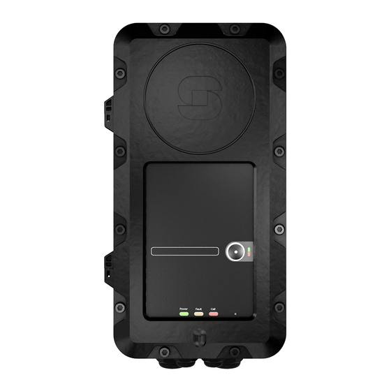
Exigo Ex Access Panels & Turbine Ex Intercoms
Product Overview
Mounting procedures are the same for all units in the Exigo and Turbine Ex series.
EAPFX-6
EAPFX-1
1023221516
1023221511
Contents of this Delivery
The unit comes with 4 blind plugs already mounted. The front frame is fastened with 2 socket-head cap M6 screws.
10 socket-head
cap M6 screws
(+ 2 fastened to
front frame)
1 Ex Unit
Important Notes before Mounting
Improper installation and operation of the Ex unit will result in the invalidation of the warranty.
The enclosure/housing must not be opened when the unit is powered.
The installation and connection of Ex units may only be carried out by qualified/approved personnel
General Mounting Considerations
When the Ex unit is mounted directly onto a wall or mounting plate, it shall rest only on the fastening points provided for
this purpose. The surface must be even and flat.
The unit must be mounted on a surface to prevent access from the rear of the unit.
Do not use countersunk screws.
Due to the cabinet material, use as low a tightening torque as possible when mounting the unit to the surface (1.5 Nm max.)
Washers are recommended.
Do not use more than 2.5 Nm torque when fastening the 12 screws into the front frame.
On Mounting Plate or Column - recommended screws:
M5 x 20 or 25 with Philips head DIN7985 or Torx. Head diameter: 10 mm.
On Wall - recommended screws:
Panhead – DIN7981 for plug or wooden wall, etc. Head diameter: 10.8 B5.5 x 38 or 45 mm.
Mounting Manual
TFIX-1
TFIX-2
1008123010
1008123020
1 Cable Gland
M25 Ex e
1 Cable Gland
M16 Ex e
TFIX-3
TFIX-4
1008123030
1008123040
Exigo Ex Access Panels & Turbine Ex Intercoms
This Manual
Mounting manual
Station overview
Installation procedures are the same for all panels in the Industrial Ex series.
EAPFX-1
EAPFX-6
TFIX-1
TFIX-2
TFIX-3
1023221511
1023221516
1008123010
1008123020
1008123030
Contents of this delivery
Note! The unit are equipped with four blind plugs, front frame is fastened with 2 unbraco M6 screws
1x Cable Gland
10 x Unbraco
M25 ATEX e
screw M6
1x Cable Gland
1x Ex Station
M16 ATEX e
This manual
Important notes before mounting
Improper installation and operation of the Ex access panel will result in the invalidation of the guarantee.
The enclosure/housing must not be opened when the product is powered.
The installation and connection of Ex units may only be carried out by qualifi ed / Approved personnel
Mounting, general
When the Ex Product is mounted directly onto a wall or mounting plate, it shall rest only on the fastening points provided for
this purpose. The surface must be even and fl at.
The unit must be mounted on a surface to prevent access from the back
Do not use countersunk screws.
Due to the cabinet material, use as low a tightening torque as possible
Washers are recommended
Do not use more than 2.5 Nm torque when fastening the 12 screws in the front frame.
On Mounting plate or column, recommended screws:
M5 x 20 or 25 with Philips head DIN7985 or Torx. Head diameter 10mm.
On Wall, recommended screws:
Panhead – DIN7981 for plug or wooden wall, etc. Head diameter 10.8 B5.5 x 38 or 45 mm
Advertisement
Table of Contents

Related Manuals for Vingtor Stentofon Exigo Ex EAPFX-1


Summary of Contents for Vingtor Stentofon Exigo Ex EAPFX-1
- Page 1 Exigo Ex Access Panels & Turbine Ex Intercoms Mounting Manual Product Overview Mounting procedures are the same for all units in the Exigo and Turbine Ex series. EAPFX-6 TFIX-1 TFIX-2 TFIX-3 EAPFX-1 TFIX-4 1023221516 1008123010 1008123020 1008123030 1023221511 1008123040 Contents of this Delivery The unit comes with 4 blind plugs already mounted.
- Page 2 Dimensions Opening the Enclosure Loosen the 2 screws Open the enclosure by Pull the right side of the front securing the front frame pulling the front frame out 5 frame to open the enclosure fully. to the on-wall box. mm, keeping it parallel to the Do NOT open the enclosure to the on-wall box.
- Page 3 Mounting the Unit Location Preparation for Drilling Make sure there is a clearance of The four mounting holes in the on- minimum 230 mm on the left for frame wall box are Ø6.4 mm. Distance: 298 movement. x 130 mm. Size of hole to be drilled depends on whether it is wall or column mounting.
- Page 4 In order to ensure the required minimum degree of protection, Mounting Cable Gland the cable glands must be tightened securely. Remove two blind plugs and insert one M16 Ex e and one M25 Ex e cable gland. Over-tightening can impair the degree of protection and Make sure to tighten sufficiently to attain damage the Ex unit.
Need help?
Do you have a question about the Exigo Ex EAPFX-1 and is the answer not in the manual?
Questions and answers