Advertisement
1
Turbine IP Video Stations
This document specifies the dimensions, mounting procedure, and camera field of view of the Turbine IP
Video Stations. The Turbine Video series comprises the following stations & accessories:
ITEM NUMBER
1008115020
1008115030
1008115060
1008140010
1008140020
1008140050
TCIV-2
1.1
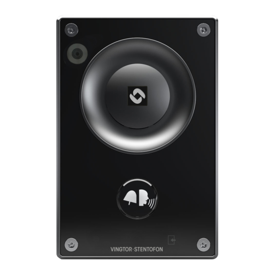
TCIV Station Dimensions
TCIV Turbine IP Video
Mounting Manual
TYPE
ITEM NAME
TCIV-2
Turbine Compact IP Video - stainless steel front plate
TCIV-3
Turbine Compact IP Video - thermoplastic front plate
TCIV-6
Turbine Compact IP Video - thermoplastic front plate with PMOLED display
TA-1
Turbine On-Wall Back Box
TA-2
Turbine Flush Mount 2-Gang Double-Depth Backbox
TA-5
Turbine Bracket for Flush Mount Backbox
96 mm
3.78"
120 mm
4.72"
TCIV-3
TCIV-6
52 mm
20.5 mm
2.05"
0.81"
Advertisement
Table of Contents

Related Manuals for Vingtor Stentofon TCIV-2


Summary of Contents for Vingtor Stentofon TCIV-2
- Page 1 This document specifies the dimensions, mounting procedure, and camera field of view of the Turbine IP Video Stations. The Turbine Video series comprises the following stations & accessories: ITEM NUMBER TYPE ITEM NAME 1008115020 TCIV-2 Turbine Compact IP Video - stainless steel front plate 1008115030 TCIV-3 Turbine Compact IP Video - thermoplastic front plate 1008115060...
- Page 2 On-Wall Surface Mounting On-Wall Surface Mount Backbox - TA-1 Mounting Hole Mounting Hole 25 mm 1” Mounting holes are to be drilled as shown. Max. recommended screw diameter: ISO M6 or ANSI 1/4". Screw length must be greater than 25 mm or 1". A4 stainless steel socket head screws/bolts are recommended.
-
Page 3: Flush Mounting
Flush Mounting Flush Mount 2-Gang Double-Depth Backbox - TA-2 1.81? 0.98? 46 mm 25 mm 89 mm / 3.50? 96 mm / 3.78? 23 mm 0.90? SIDE L It is recommended to utilize backboxes with weep holes at the bottom. Flush Mount Bracket - TA-5 L The TA-5 Bracket is mandatory for flush mounting. - Page 4 Flush Mounting Procedure L The Gasket MUST be 2-Gang Backbox L Ensure the station is mounted mounted to seal the Bracket vertically with the microphone station! aperture facing down. Gasket L Ensure there is enough clearance Turbine Station under the station so that the microphone aperture is not smothered.
Need help?
Do you have a question about the TCIV-2 and is the answer not in the manual?
Questions and answers