Vingtor Stentofon TCIS-1 Configuration Manual
Turbine compact ip stationstcis-1
Hide thumbs
Also See for TCIS-1:
- Getting started (4 pages) ,
- Technical manual (80 pages) ,
- Mounting manual (4 pages)
Table of Contents
Advertisement
Advertisement
Table of Contents

Subscribe to Our Youtube Channel
Related Manuals for Vingtor Stentofon TCIS-1


Summary of Contents for Vingtor Stentofon TCIS-1
- Page 1 Turbine Compact IP Stations Configuration Guide TECHNICAL MANUAL A100K11194...
- Page 2 This document describes the setup procedure and configuration of the various models of the Turbine Compact IP station series. Station Software Version: 3.0.3.3 or later Product Item Number Tubine Compact IP Station - TCIS-1 1008111010 Tubine Compact IP Station - TCIS-1-V 1028111010 Tubine Compact IP Station - TCIS-2...
-
Page 3: Table Of Contents
Contents 1 Turbine Compact IP Stations ......................5 2 Station Connections ........................7 2.1 External Connectors on IP Station ..................7 2.2 Power Supply .......................... 7 2.3 Network Connection ........................ 7 2.4 Input/Output Connections ....................... 7 3 Starting Up the Station ........................8 4 AlphaCom Configuration ...................... - Page 4 B.5 Front Board - Front ........................ 57 B.6 Front Board - Rear ........................ 57 Figures Figure 1 Turbine TCIS-1 Station Keys & Functions ................6 Figure 2 Turbine TCIS-6 Station Keys & Functions ................6 Figure 3 External Connectors on IP Station ..................7 Figure 4 AlphaCom Intercom System ....................
-
Page 5: Turbine Compact Ip Stations
Some of the many features include: HD voice quality, Open Duplex, Active Noise Cancellation, MEMS microphone, a 10W Class D amplifier and our unique speaker grille design. There are six station models in the Turbine Compact series: TCIS-1/TCIS-1-V TCIS-2 TCIS-3 Thermoplastic frontplate with single call... -
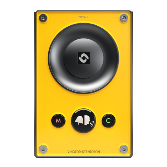
Page 6: Figure 1 Turbine Tcis-1 Station Keys & Functions
Loudspeaker Manual Speech Cancel Direction Control Call Button Microphone Figure 1 Turbine TCIS-1 Station Keys & Functions Loudspeaker PMOLED Display Scroll Down Cancel Call Button Scroll Up Microphone Figure 2 Turbine TCIS-6 Station Keys & Functions A100K11194 Turbine Station Configuration Guide... -
Page 7: Station Connections
Station Connections External Connectors on IP Station 24 VDC for external secondary power if PoE is not used. Pin 1 is positive. - COM relay - NO relay - NC relay RJ-45 - 5.3V (LED driver) port - GND - Input/Output 1 - Input/Output 2 - Input/Output 3 - Input/Output 4... -
Page 8: Starting Up The Station
● station subscribed to an AlphaCom server ● SIP station ● Pulse station iPBX (SIP domain) Control Room Master Station IP Network SIP phone Turbine TICS-5 AlphaCom XE7 Turbine TCIS-1 AlphaCom XE Server/Exchange A100K11194 Turbine Station Configuration Guide... -
Page 9: Alphacom Configuration
Control Room Master Station IP Network IP Desk Master Turbine TICS-5 AlphaCom XE7 Turbine TCIS-1 AlphaCom XE Server/Exchange Figure 4 AlphaCom Intercom System Logging into the Station Access the station by logging into the web interface using a standard web browser: 1. -
Page 10: Station Main Settings
Turbine Frontboard Depending on the type of Turbine Compact station, select one of the options from the drop-down box: - Kit - Normal (TCIS-1, TCIS-2, TCIS-3) - OLED Labels (TCIS-4, TCIS-5) - Scrolling Station (TCIS-6) Registration Settings ● Enter the IP address of the AlphaCom server/exchange in which the IP station is to be a subscriber in the AlphaCom IP-address field. -
Page 11: Advanced Alphacom Settings
- Push-To-Talk: Half-duplex communication. Initially the microphone is shut off. Push the M-button to open the microphone, and release to listen. (Only applicable to TCIS-1 station) - Open: Full Open Duplex without echo cancellation A100K11194 Turbine Station Configuration Guide... - Page 12 Line Out Source This parameter can play audio either from VoIP signal (Speaker) or direct from Microphone. Audio Profile For this parameter, there are 2 options: Normal or Advanced. ● Select Advanced to access additional and detailed menu options for audio settings such as noise and echo cancellation: Advanced Audio Settings L These parameters are optional.
-
Page 13: I/O Settings
I/O Settings ● Select Advanced AlphaCom > I/O Settings from the menu ● Select either Input or Output options from the drop-down box for I/O Pins 1 to 6. OLED Labels L Note that only Turbine stations configured with OLED Labels (TCIS-4, TCIS-5) under Main Settings will have this menu option. -
Page 14: Address Book
Address Book L Note that only the Turbine station configured as a Scrolling Station (TCIS-6) under Main Settings will have this menu option. ● Select Advanced AlphaCom > Address Book from the menu Default Display Text ● The idle text shown in the display may be changed. The default text is: Scroll to Select Font Size ●... -
Page 15: Sip Configuration
(SIP domain) SIP phone IP Network Turbine TICS-6 Turbine TICS-5 SIP phone Turbine TCIS-1 Figure 5 SIP System Logging into the Station Access the station by logging into the web interface using a standard web browser: 1. Open a web browser 2. -
Page 16: Station Main Settings
Turbine Frontboard Depending on the type of Turbine Compact station, select one of the options from the drop-down box: - Kit - Normal (TCIS-1, TCIS-2, TCIS-3) - OLED Labels (TCIS-4, TCIS-5) - Scrolling Station (TCIS-6) IP Settings ● DHCP – Select this option if the IP station shall receive IP Settings from a DHCP server. -
Page 17: Sip Settings
SIP Settings ● Select SIP Configuration > SIP Settings to access the page for configuring SIP parameters. Account Settings Display Name - Enter a name that will be shown on the display at the remote party. Directory Number (SIP ID) - This is the identification of the station in the SIP domain, i.e. the phone number for the station. - Page 18 Authentication Password - The authentication user password used to register the station to the SIP server. This is required only if the SIP server requires authentication Register interval - This parameter specifies how often the station will register, and reregister in the SIP domain. This parameter will affect the time it takes to detect that a connection to a SIP domain is lost.
-
Page 19: Audio Settings
Audio Settings Select SIP Configuration > Audio Settings Speaker Volume - Select the volume level in the range 0 to 7 from the drop-down menu. - Default setting is 5 Noise Reduction Level - The higher the noise reduction level the more deterioration there is in audio quality. - Page 20 - Push-To-Talk: Half-duplex communication. Initially the microphone is shut off. Push the M-button to open the microphone, and release to listen. (Only applicable to TCIS-1 station) - Open: Full Open Duplex without echo cancellation Audio Profile For this parameter, there are 2 options:...
-
Page 21: Direct Access Key Settings
Direct Access Key Settings ● Select SIP Configuration > Direct Access Key Settings to access the page for configuring DAKs. Direct Access Key Settings Direct Access Key 1 - Direct Access Key 2 Enter the number to call in the Value field. L Note that the availability of this parameter depends on the Turbine station type selected such as OLED Labels, Normal, Scrolling Station under Main Settings. -
Page 22: Relay Settings
Input Button 2 This is the SIP ID for the extension to be called when call button no. 2 is pressed, i.e. the SIP ID number of the receiving party. Input Button 3 This is the SIP ID for the extension to be called when call button no. 3 is pressed, i.e. -
Page 23: Snmp Settings
SNMP Settings SNMP (Simple Network Management Protocol) is a protocol for centralizing the management of devices in IP networks. ● Select Advanced Network > SNMP to access the page for configuring SNMP parameters. SNMP Settings Enable SNMP v1 - This enables reading of the MIB using SNMP version 1. Enable SNMP v2c - This enables reading of the MIB using SNMP version 2c. - Page 24 SNMP Trap Settings Trap receiver - Enter the IP address of the server receiving SNMP traps. This is disabled if the field is left empty. Enable SNMP Traps IP-Station Started - If enabled, the station will send an SNMP trap when the station application is started.
- Page 25 Input Button Released - If enabled, the station will send an SNMP trap when an input is deactivated. Dak Pressed - If enabled, the station will send an SNMP trap when a DAK is pressed. Dak Released - If enabled, the station will send an SNMP trap when a DAK is released.
-
Page 26: Automatic Configuration Using Tftp
Automatic Configuration using TFTP A SIP station may be set up to automatically poll configuration settings for SIP, Call and SNMP from a TFTP server. The IP address of this TFTP server can be obtained using DHCP procedures or be manually configured. Before you start the automatic configuration procedure: ●... -
Page 27: Pulse Configuration
Pulse Configuration STENTOFON Pulse is an IP-based intercom system for upto 16 intercom stations. The system works with all STENTOFON IP intercom stations. Turbine IP Station - Pulse Server Directory Number: 10 Name: Reception Desk IP Address: 169.254.1.99 Turbine IP Station Directory Number: 12 Name: Rear Entrance IP Address: 169.254.1.103... -
Page 28: Station Main Settings
Turbine Frontboard Depending on the type of Turbine station, select one of the options from the drop-down box: - Kit - Normal (TCIS-1, TCIS-2, TCIS-3) - OLED Labels (TCIS-4, TCIS-5) - Scrolling Station (TCIS-6) IP Settings ● DHCP – Select this option if the IP station shall receive IP Settings from a DHCP server. -
Page 29: Connect Other Intercom Stations
Connect other Intercom Stations Connect all other IP intercom stations to the network. Note that all other IP intercom stations have to be on the same LAN (IP subnet) as the Pulse Server. Wait for the stations to boot up (approximately 60 seconds) before proceeding to the next step. -
Page 30: Configure Call And Audio Settings
Configure Call and Audio Settings It is optional to configure the call and audio settings. Default settings will be used if they are not configured. ● Select Server Management > Server Configuration > Call and Audio Settings The Call and Audio Settings menu include the following parameters: Autoanswer Auto-answer is typically enabled for substations and not for master stations. -
Page 31: Rd -Party Ip Telephone And Ip Dect
● Select the station on which you want to program the Call Button - The Call Button is Input Button 1 ● Under Value enter the directory number to call when the button is pressed. If you want to use also input 2 (Key 2) and input 3 (Key 3), simply enter the required value for Input Button 2 and Input Button 3. -
Page 32: Configure Ip Telephone
● Under Third Party SIP Terminals enter the Directory Number, Name, and Profile for the IP telephone. ● Click Add followed by Save 6.8.2 Configure IP telephone You now have to log into the 3rd-party IP telephone to configure the SIP account to register it with the Pulse Server station. The Directory Number and Password (SIP Account) created in section 6.8.1 is used to register the 3rd-party station with the Pulse Server. -
Page 33: Modify Pulse Station Profiles
6.10 Modify Pulse Station Profiles The Station Profile defines a set of service features and parameters that are available for a group of stations. The Pulse system can have five station profiles: ● Profile 1 - Default ● Profile 2 - Substation ● Profile 3 - Display station ●... -
Page 34: Common Advanced Network Settings
Common Advanced Network Settings L The configuration settings described in this section are not mandatory. Network Access Control IEEE 802.1X is an IEEE Standard for Port-based Network Access Control (PNAC). By “port” we mean a single point of attachment to the LAN infrastructure. -
Page 35: Station Software Upgrade
Station Software Upgrade There are two ways of upgrading the software on the IP station: ● Uploading the software via the web interface of the station ● Uploading the software via AlphaWeb on the AlphaCom server Prerequisites Both upgrade methods require that an TFTP Server is available and that the latest software image files have been downloaded from Zenitel’s support website (AlphaWiki). -
Page 36: Upgrade Via Alphacom Xe
● Click the Upgrade button to upgrade the software on the IP station. The upgrade procedure takes about 3 minutes. The process can be monitored by clicking the Log viewer tab in the TFTP server program. Upgrade Via AlphaCom XE ●... -
Page 37: Station Indication Leds
Station Indication LEDs LEDs on Front Plate Status LEDs - Bell icon lights yellow when a call is placed and ringing - Talk icon lights green when a call is active and in conversation - Door icon lights red when the door is unlocked or relay is active Talk Icon: Flashing at 1 second intervals - Station has no connection to the AlphaCom server/exchange. -
Page 38: Restoring Factory Defaults
10 Restoring Factory Defaults A Turbine IP Station may have to be reset to its original factory default settings if, for instance, the password to the station web interface is forgotten. The defaults can either be set to Activated DHCP or Static IP. 10.1 Reset to Factory Default Settings with Activated DHCP 1, 2, 3, 4, 5... -
Page 39: Compact Station & Accessories Dimensions
11 Compact Station & Accessories Dimensions 11.1 Compact Station Dimensions Dimensions (HxWxD) Weight TCIS-1, TCIS-3, TCIS-4, 180 x 120 x 70 mm 0.8 kg TCIS-5, TCIS-6 TCIS-2 180 x 120 x 70 mm 1 kg 96 mm 20.5 mm 52 mm 3.78”... -
Page 40: Flush Mount Bracket - Ta-5
11.3 Flush Mount Bracket - TA-5 L The TA-5 Bracket is mandatory for flush mounting. CUTOUT 4 mm 0.16” 46 mm 1.81” 4 mm 0.16” 91 mm 3.58” Fits US 2-GANG electrical boxes. Recommended screw diameter: up to M4 (5/32") Use screw recommended by back box manufacurer. -
Page 41: Turbine Station Specifications
12 Turbine Station Specifications The technical specifications apply to the Turbine Compact IP Station series: TCIS-1/ TCIS-1-V, TCIS-2, TCIS-3, TCIS-4, TCIS-5, TCIS-6. AUDIO Audio quality - speech transmission index (STI) - at 70 dB > 0.8* Audio quality - percentage articulation loss of consonants (Alcons) <... - Page 42 NETWORKING AND PROTOCOLS Protocols IPv4 (with DiffServ), SIP, TCP, UDP, HTTPS, TFTP, RTP, DHCP, SNMP, STENTOFON CCoIP® , NTP LAN protocols Power over Ethernet (IEEE 802.3 a-f) VLAN(IEEE 802.1pq) Network Access Control (IEEE 802.1x) STP (IEEE 802.1d) RSTP (IEEE 802.1d-2004) Management and operation HTTP/HTTPS (Web configuration) DHCP and static IP + STENTOFON Pulse™...
-
Page 43: A: Configuration File Parameters For Sip Provisioning
A: Configuration File Parameters for SIP Provisioning A.1 Remote Provisioning using TFTP An IP station may be set up to automatically poll configuration from a TFTP server. The IP address of this TFTP server can be obtained using DHCP procedures or be manually configured. The IP station will first try to download the global configuration file: ipst_config.cfg Then the IP station will download a device specific configuration file: ipst_config_01_02_03_04_05_06.cfg... -
Page 44: Sip Parameters
A.3 SIP Parameters nick_name Required: No. Defaults to sip_id. Description: The nickname for the station can be used to assign a logical name to the station. For example, a station belonging to James may be assigned the nickname “James” or “James’ station”. Values: Text string. -
Page 45: Call Parameters
sip_outbound_proxy Required: Optional Description: Configures an outbound proxy server that receives all initiating request (INVITE and SUBSCRIBE) messages. Values: IP address given in regular dot notation, e.g. 10.5.2.100 sip_outbound_proxy_port Required: If proxy server is defined. Default is 5060. Description: The UDP port on the SIP proxy server. Values: Integer. - Page 46 of the receiving party. Next value on the Ringlist 2 is ringlist2_value2, ringlist2_value3 etc. Values: String value ringlist3_value1 Required: Yes Description: This is the SIP ID for the extension to be called when the first call button is pressed and ringlist is used, i.e. the telephone number of the receiving party.
- Page 47 dak1_value Required: Yes Description: This is the SIP ID for the extension to be called when the first call button is pressed is used, i.e. the telephone number of the receiving party. Values: String value dak1_option Required: Yes Description: Decides which ringlist the button use. Values: Integer value.
-
Page 48: Relay Parameters
rtp_timeout Required: No. Defaults to 0. Description: Cancels a call if the station does not receive RTP. Values: Integer value: 0-9999 seconds. 0 = RTP timeout disabled. remote_controlled_volume_override_mode Required: No. Description: Acts as a simplex mode after first DTMF * or # is received from remote station. -
Page 49: Snmp Parameters
relay1_dtmf_timed_relay_duration Description Duration to keep the relay active Values: Integer. relay1_event_out_ringing Description Which state the relay should be set to during outgoing ringing. Values: Integer, 0 = no change, 1 = activated, 2 = deactivated, 3 = slow flash, 4 = fast flash relay1_event_inc_ringing Description Which state the relay should be set to during incoming ringing. - Page 50 Values: IP address given in regular dot notation, e.g. 10.5.2.100. For example, with an allowed network of 10.5.2.0 and a network mask of 24, anyone with IP address 10.5.2.0 to 10.5.2.255 can access the MIB. network_mask Required: No. Description: The mask used to determine the allowed network for reading the MIB.
- Page 51 enable_callConnectFailed Required: No. Defaults to 1. Description: If enabled, the station will send an SNMP trap if an incoming call to the station fails to connect for any reason (busy etc.). Values: 0 = disabled, 1 = enabled. enable_callDisconnect Required: No. Defaults to 1. Description: If enabled, the station will send an SNMP trap when a call is disconnected.
-
Page 52: Example Configuration File
enable_relayDeactivated Required: No. Description: If enabled, the station will send an SNMP trap when a relay has been deactivated Values: 0 = disabled, 1 = enabled A.7 Example Configuration File [general] auto_update_interval=10 auto_update_image_type=tsi-3.0.1.50 Only for Turbine (8121) auto_update_image_type=A100G80200.01_10_1_2.bin Only for 8020-8024 auto_update_image_crc=C1466499 Only for 8020-8024 [sip] nick_name=Testname... - Page 53 remote_controlled_volume_override_mode=1 Accepted values 0 or 1. auto_answer_mode=1 Accepted values 0 or 1. auto_answer_delay=10 Value: 0 < seconds < 30 [relays] relay1_dtmf_timed_relay=5 relay1_dtmf_timed_relay_duration=10 relay1_event_inc_ringing=1 relay1_event_inc_call=2 relay1_event_idle=1 [snmp] trap_receiver=10.5.2.219 network=10.5.2.0 network_mask=24 community=public enable_v1=1 Accepted values 0 or 1. enable_v2c=1 Accepted values 0 or 1. enable_ipsStarted=1 Accepted values 0 or 1.
-
Page 54: B: Station Board Connections & Indicators
B: Station Board Connections & Indicators B.1 PCB - Front RJ45 PoE port for 10/100 Mbit Ethernet connection. The station can be powered from this port if the line supports Power over Ethernet (PoE). 24V EXT 5-pin plug-on terminal for external connections. 0V EXT Pin 1/2 24 VDC for external secondary power if PoE... -
Page 55: Input Connectors
B.2 Input Connectors 5.3V 10-pin plug-on terminal for external connections. Pin 1 5.3V I/O 1 Pin 2 Pin 3 Button Input or LED Driver I/O 2 Pin 4 Button Input or LED Driver I/O 3 Outputs (1) Pin 5 Button Input or LED Driver I/O 4 Pin 6 Button Input or LED Driver... -
Page 56: Pcb - Rear
B.4 PCB - Rear 10-pin terminal for digital MEMS Microphone Pin 1 Left mic select (Vdd) Pin 2 Right mic select (GND) Pin 3 Data Pin 4 Data Pin 5 Vdd 3.3V Pin 6 Vdd 3.3V Pin 7 Pin 8 Pin 9 Pin 10 A100K11194... -
Page 57: Front Board - Front
B.5 Front Board - Front B.6 Front Board - Rear A100K11194 Turbine Station Configuration Guide... - Page 58 www.stentofon.com Zenitel Norway AS P.O. Box 4498 Nydalen NO-0403 OSLO Norway support@stentofon.com DOC NO. A100K11194 support@vingtor.com Zenitel and its subsidiaries assume no responsibility for any errors that may appear in this publication, or for damages arising from the information therein. STENTOFON and VINGTOR products are developed and marketed by Zenitel.
Need help?
Do you have a question about the TCIS-1 and is the answer not in the manual?
Questions and answers