Table of Contents
Advertisement
Quick Links
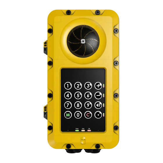
Contents of this Delivery
The unit comes with 5 blind plugs already mounted. The front frame is fastened with 2 socket-head cap M6
screws.
TFIE-1 1008122010
Important Notes before Mounting
Improper installation and operation of the unit will result in the invalidation of the warranty.
The enclosure/housing must not be opened when the unit is powered.
The installation and connection of units may only be carried out by qualified/approved personnel
General Mounting Considerations
When the unit is mounted directly onto a wall or mounting plate, it shall rest only on the fastening points provided for
this purpose. The surface must be even and flat.
The unit must be mounted on a surface to prevent access from the rear of the unit.
Do not use countersunk screws.
Due to the enclosure material, use as low a tightening torque as possible when mounting the unit to the surface
(1.5 Nm max.)
Washers are recommended.
Do not use more than 2.5 Nm torque when fastening the 12 screws into the front frame.
On Mounting Plate or Column - recommended screws:
M5 x 20 or 25 with Philips head DIN7985 or Torx.
Head diameter: 10 mm.
On Wall - recommended screws:
Panhead – DIN7981 for plug or wooden wall, etc.
Head diameter: 10.8 B5.5 x 38 or 45 mm.
Turbine Industrial Intercoms
Mounting Manual
TFIE-2 1008122020
TFIE-6 1008122060
1 Cable Gland M20 1P68
1 Cable Gland M16 1P68
10 socket-head cap M6 screws
(+ 2 fastened to front frame)
This Manual
Advertisement
Table of Contents

Related Manuals for Vingtor Stentofon TFIE-1


Summary of Contents for Vingtor Stentofon TFIE-1
- Page 1 (+ 2 fastened to front frame) TFIE-2 1008122020 TFIE-6 1008122060 This Manual TFIE-1 1008122010 Important Notes before Mounting Improper installation and operation of the unit will result in the invalidation of the warranty. The enclosure/housing must not be opened when the unit is powered.
- Page 2 Dimensions Opening the Enclosure Loosen the 2 screws Open the enclosure by Pull the right side of the front securing the front frame pulling the front frame out 5 frame to fully open the enclosure. to the on-wall box. mm, keeping it parallel to the Do NOT open the enclosure to the on-wall box.
- Page 3 Mounting the Unit Location Preparation for Drilling Make sure there is a clearance of The four mounting holes in the on- minimum 230 mm on the left for wall box are Ø6.4 mm. Distance: 298 frame movement. x 130 mm. Size of hole to be drilled depends on whether it is wall or column mounting.
- Page 4 EMMAI-2H Connection Manual A100K11567 TA-23 Connection Manual A100K11457 AutoCAD Dwg. TFIE-1 Turbine Industrial IP and SIP Intercom Station A100K11503 AutoCAD Dwg. TFIE-2 Turbine Industrial IP and SIP Intercom Station A100K11754 AutoCAD Dwg. TFIE-6 Turbine Industrial IP and SIP Intercom Station DOC NO.
Need help?
Do you have a question about the TFIE-1 and is the answer not in the manual?
Questions and answers