
Related Manuals for LifeFitness Synrgy 180 Personal


Summary of Contents for LifeFitness Synrgy 180 Personal
- Page 1 Synrgy 180 Personal S180P Owner's Manual/Assembly Instructions 1013910-0001 REV AA...
- Page 3 Corporate Headquarters Columbia Centre III, 9525 West Bryn Mawr Avenue, Rosemont, Illinois 60018 • U.S.A. 847.288.3300 • FAX: 847.288.3703 Service phone number: 800.351.3737 (toll-free within U.S.A., Canada) Global Website: www.lifefitness.com International Offices AMERICAS United Kingdom All Other EMEA Countries and Distributor...
- Page 4 User and Service Documents Link https://www.lftechsupport.com/web/document-library/documents Additional information is available online using the link above. أ علاه إل ر إبط باستخدإم إ لإ ن تر نت على إضافية معلومات تتوفر 点击上面的链接可在线获取更多信息。 Flere oplysninger er tilgængelige online gennem linket ovenfor. Bijkomende informatie is online beschikbaar via bovenstaande link. Vous trouverez plus d'informations en ligne à...
-
Page 5: Table Of Contents
Corporation. Disclaimer: Images and specifications are current as of the date of publication and are subject to change. Columbia Center III - 9525 West Bryn Mawr Ave., Rosemont, IL 60018 • 847-288-3300 • www.lifefitness.com • 1013910-0001 AA • 2019 Page 3 of 33... -
Page 6: Safety Information
1. Safety Safety Information Operating Warnings WARNING: This product can expose you to chemicals including Methyl Isobutyl Ketone, which is known to the State of California to cause cancer and birth defects or other reproductive harm. For more information go to http://www.P65Warnings.ca.gov •... -
Page 7: Warnings And Cautions
• Contact a Life Fitness representative with any questions regarding proper weights and loading. Warnings and Cautions Warning labels indicate a potentially hazardous situation that could result in serious injury or death if the precautions are not observed. Caution labels indicate a potentially hazardous situation that could result in serious injury or damage to machine if the precautions are not observed. -
Page 8: Assembly
2. Assembly Tools Required Item Description Qty. 1/2" Wrench 3/4" Wrench 6mm Wrench 17mm Wrench 3mm Hex Wrench 7mm Hex Wrench #2 Phillips Screwdriver Rubber Mallet Bolt to Floor Guide section for required anchoring tools. Page 6 of 33... -
Page 9: Option Categories
Option Categories Item Description Shelf Option Shelf Options Item Description Dual Rail Shelf Accessory Shelf Digital Coach Mounting Shelf Page 7 of 33... -
Page 10: Shelf Storage Compatibility
Shelf Storage Compatibility Shaded sections signify the occupied positions of the shelf option with its accessories. *Digital Coach Mounting Shelf must be moved down one hole if Accessory Shelf is to be used in the 5th shelf position. Page 8 of 33... -
Page 11: Shelf Option Clearance
Shelf Option Clearance Shelf Spacing • Ensure shelves have minimum spacing requirements, shown in table above, by counting bolt holes between the top bolt of the lower shelf and the bottom bolt of the shelf above it. • Above bolt hole spacing table are recommended positions. S180P allows for various shelf positioning based on your accessories. -
Page 12: Components
Components Item Description Qty. Upright Left Chin End Plate/Suspension Anchor Right Chin End Plate/Suspension Anchor Left Foot Cover Right Foot Cover End Cap Suspension Anchor Chin Option Cover Foam Roller/Mat Storage Suspension Chin Page 10 of 33... -
Page 13: Hardware List: Uprights And Shelves
Hardware List: Uprights and Shelves Upright Hardware Item Description Qty. Socket Nut 1/4" Spacer Retainer M10 X 80mm Screw 7/16" Hole Plug 8 x 3/4" Screw Grommet Floor Anchor Shelf Hardware (Accessory and Dual Rail) Item Description Qty. Socket Nut 1/4"... -
Page 14: Hardware List: Digital Coach Mounting Shelf
Hardware List: Digital Coach Mounting Shelf Item Description Qty. Retainer Socket Nut 1/4" Spacer Tie Wrap 3/8" Washer M10 X 1.5 X 80 Screw M10 X 1.5 X 25 Screw M3.5 X 12 Phillips Screw M3.5 Washer M3.5 Nut Page 12 of 33... -
Page 15: Suspension Chin
Suspension Chin Install Suspension Chin: 1. Loosely install Suspension Chin and hardware. Item Description Qty. Upright Socket Nut Suspension Chin Chin End Plate/Suspension Anchor (left and right) Retainer M10 X 80mm Screw 2. Chin End Plate/Suspension Anchor on the left or right side: Ensure tab is orientated as shown below. -
Page 16: Lower Shelf
Lower Shelf Install Shelf Option (Accessory or Dual Rail) and Foam Roller/Mat Storage: Loosely install Shelf A, Foam Roller/Mat Storage and hardware, using holes 8, 6 and 4 (holes 8, 7 and 5 for Dual Rail). Item Description Qty. Lower Shelf A (Accessory Shelf or Dual Rail Shelf, not shown) Socket Nut 1/4"... - Page 17 Item Description Qty. Upright Socket Nut 1/4" Spacer Retainer M10 X 80mm Screw Page 15 of 33...
-
Page 18: Digital Coach Mounting Shelf
Digital Coach Mounting Shelf Install Digital Coach Mounting Shelf Option, if equipped: 1. Loosely install Digital Coach Brackets and hardware, using holes 25 and 19 (use holes 24 and 18 if an Accessory Shelf is to be used above Digital Coach). Item Description Qty. - Page 19 3. Mount Monitor or iPad ® (not supplied) to the Bracket/Media Mount. For Monitor use: For iPad ® use: NOTE: Refer to Bracket instructions for installation details. Item Description Qty. Monitor/iPad ® (not supplied) Bracket/Media Mount 4. For Monitor use: Fasten Electrical Power Block (not supplied) to Media Mount Tabs Item Description Qty.
- Page 20 5. Fasten Electrical Cord to Media Mount. For Monitor use: For iPad ® use: Item Description Qty. Media Mount Electrical Cord (not supplied) Tie Wrap 6. Slide Media Mount onto Media Center Brackets For Monitor use: For iPad ® use: Item Description Qty.
- Page 21 7. Loosely install hardware, affixing the Media Mount. For Monitor use: For iPad ® use: Item Description Qty. M10 X 1.5 X 25 Screw 3/8 Washer Media Mount iPad ® is a registered trademark of Apple Inc. Page 19 of 33...
-
Page 22: Top Shelf
Top Shelf Install Shelf Options (Accessory or Dual Rail): With Digital Coach Mounting Shelf: • Loosely install Shelf D and hardware, using holes 27 and 26 (holes 28 and 26 for Accessory Shelf). Without Digital Coach Mounting Shelf: • Loosely install Shelf D and hardware, using holes 26 and 25 (holes 27 and 25 for Accessory Shelf). Shown with Digital Coach Mounting Shelf: Shown without Digital Coach Mounting Shelf: NOTE: Tighten hardware to 30-39 IN-LBS. -
Page 23: Final Assembly (Digital Coach And Storage)
Final Assembly (Digital Coach and Storage) Follow these steps to complete assembly. 1. Tighten all loosely assembled hardware: Torque hardware to 18-20 FT-LBS (24.4-27.1 Nm). 2. Anchor unit to floor: Refer to Bolt to Floor Guide in this manual for further details. Item Description Qty. - Page 24 3. Attach Foot Covers: Install Foot Covers and hardware. Item Description Qty. Left Foot Cover Right Foot Cover 8 X 3/4" Screw Grommet NOTE: Left Foot Cover must be installed first. NOTE: Tighten hardware to 30-39 IN-LBS. (3.9-4.4 Nm). 4. Attach End Caps and Hole Plugs (where applicable): Fill all holes with End Caps and Hole Plugs;...
-
Page 25: Variations
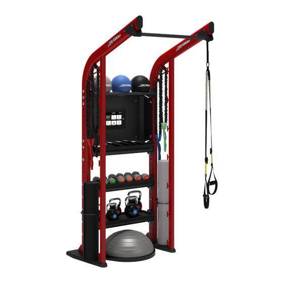
3. Variations S180P Example Packages Item Description S180P Digital Coach S180P Storage Each package comes standard with the options shown in the respective images. Page 23 of 33... -
Page 26: Product Information
4. Product Information Footprint and Live Area Component Weight Load Rating Footprint (D x W x H) Live Area (D x W x H) S180P 185 lbs 46.5" x 44.5" x 94" 12' x 83.5" x 105.5" 83.9 kg 118cm x 113cm x 239cm 366cm x 212cm x 268.5cm Accessory Shelf 41.5 lbs... -
Page 27: Maintenance Procedures
Wipes on the equipment for at least 2 minutes for general disinfection purposes. Contact Customer Support Services to order these cleaners (1-800-351-3737 or email: customersupport@lifefitness.com). Mild soap and water or a mild non-abrasive household cleaner can also be used to clean the display and all exterior surfaces. -
Page 28: Warranty
6. Warranty What is Covered This Life Fitness commercial exercise equipment product is warranted to be free of all defects in material and workmanship. Who is Covered The original purchaser or any person receiving the product as a gift from the original purchaser. Who Pays Transportation and Insurance For Service If the Product or any covered part must be returned to a service facility for repairs, We, Life Fitness, will pay all transportation and insurance charges for the first year. -
Page 29: Warranty Coverage
Warranty Coverage NOTE: There is no warranty coverage for labor on Strength Products. Item 10 Years 5 Years 1 Year 90 Days Frame Hardware / Mechanical Items Not Specified Page 27 of 33... -
Page 30: Bolt To Floor Guide
7. Bolt to Floor Guide Introduction Life Fitness designs its products to be stable when used as designed. Because strength training is dynamic, we cannot predict how users will ultimately use the products in all circumstances. Therefore, Life Fitness requires that strength training equipment be secured to a solid, level surface to stabilize and eliminate rocking or tipping over. -
Page 31: Safety Pullout Force
Anchor Types Subfloor thickness between unit and concrete Anchor 0” - 3/4” (0mm - 19.1mm) 3/4” - 1.0” (19.1mm - 1.0” - 7.0” (25.4mm - 25.4mm) 178mm) HSL-3 M 8/40 HST M12 x 115/20 to HST M12 x 295/200 (length depends on subfloor thickness) •... -
Page 32: Tools Required
Selected Anchor Design Resistance in Tension * KH-EZ ¼” x 4” 830 lb HUS-H 6MM x 120MM 3.3 kN KH-EZ 3/8” x 4” 1535 lb KH-EZ 3/8” x 5” 1535 lb HUS-H 8MM x 120MM 3.3 kN HUS-H 8MM x 150MM 3.3 kN HSL-3 M 8/40 2000 lb... -
Page 33: Dynamic Hsl-3 8/40 Anchor Procedure
Dynamic HSL-3 8/40 Anchor Procedure 1. Place unit into position to be mounted. 2. Wearing protective glasses, drill down into flooring perpendicularly to the required depth, ensuring that the foot thickness is being accounted for; refer to Anchor Selection and Foot Dimensions Section. 3. -
Page 34: Dynamic Hst Safety Stud Anchor Procedure
Dynamic HST Safety Stud Anchor Procedure 1. Place unit into position to be mounted and cycle unit to set stance. 2. If necessary, cut HST Safety Stud Anchor to length before installation, leaving enough length to ensure proper concrete embedment (see Anchor Section for embedment depth required) and proper tightening torque (44 Foot- Pounds/60Nm). -
Page 35: Foot Dimensions
Foot Dimensions Use below image to determine foot specifications. Page 33 of 33...
Need help?
Do you have a question about the Synrgy 180 Personal and is the answer not in the manual?
Questions and answers