
Subscribe to Our Youtube Channel
Related Manuals for Pilot Communications Skyline 182


Summary of Contents for Pilot Communications Skyline 182
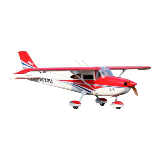
- Page 1 Assembly Manual For Skyline 182 Wingspan: 88 in Wingarea: 1479.8 sp in Length: 78.8 in Engine: 50CC www.pilot www.pilot- - rc.com rc.com...
-
Page 2: Introduction
INTRODUCTION Thank you for purchasing our Skyline 182. we strive to achieve the real Quick Builded and ARF aircraf . It just requires the least amount of assembly of any kit that almost finished in factory. To obtain the perfect... -
Page 3: Warranty
WARRANTY WARRANTY ■ All Pilot-RC products are guaranteed against defects for 30 days of receiving your airplane. This warranty is limited to construction or production defects in both material and workmanship , it does not cover any component parts damaged through use or modification . -
Page 4: Attention
ATTENTION ATTENTION Do not regard this plane as a toy! ■ ■ To ensure safety, please read the instruction manual thoroughly before assembly. ■ Building and operating an RC Plane of this nature requires previous experience and competence to an experienced level. -
Page 5: Table Of Contents
INDEX Introduction ………………….………..….…….…. Warranty …………………….……..….…..……. Attention …………….…………..….……..……. Fuselage Unit Landing Gear Assembly Front landing Gear Installation ………….…..……. Rear landing Gear Installation …………..….……… Servo Unit Wing Servo Assembly ………….….………. Rudder Assembly ………….……….….. Elevator Servo Assembly ………….……………. Engine Unit Firewall Assembly ……….……..………. Engine Assembly ……….…..……..……... -
Page 6: Landing Gear Assembly
Landing Gear Assembly Front Landing Gear Installation... - Page 7 Front Landing Gear Assembly 1, there are 6 holes in the bottom of 3. Inside view of mounting front the engine box which are for the landing gear. front landing gear. 4 Outside view of mounting front 2. Mount the front landing gear to landing gear.
- Page 8 Front Landing Gear Assembly 5. Install the servo for front landing gear. Put the servo to the servo bay 7. Adjust the rod length to make the which is on the back of the firewall. front wheel in the middle place. 8.
- Page 9 Front Landing Gear Assembly 9. Take off this bolt. 10. Take off the bottom part of the 11. Install the tire into the front landing gear . landing gear with the circlips outside.
- Page 10 Front Landing Gear Assembly Install the front wheel pants: Note: the front wheel pants are 2. Put the pants into the front different shape from the rear landing gear . wheel pants. 3. Screw two side bolt to fit the wheel 1.
- Page 11 Rear Landing Gear Assembly 1. Install the landing gear with the 3. Install the landing gear axles with bolts and locking nuts. Do not over lock nut. tighten the hardware. 2. Put two plastic parts for the 4. Make the flat sides of the axle bolt landing gear into the landing gear vertical with grond .Then tighten the...
- Page 12 Rear Landing Gear Assembly 5. Install wheels and wheel collars 7. Finish the wheel pants mounting using Blue Loctite on the set screws. with the bolts. 8. Glue the plastic part for the 6. Drill the holes for the mounting landing gear to the fuselage.
- Page 13 Rear Landing Gear Assembly 9. Glue the plastic part to the wheel pants.
-
Page 14: Wing Servo Assembly
Wing Servo Assembly Wing Servo Assembly Servo Arm Installation 2. Ensure the servo arm is 90 Minimum Request Servo: degrees with servo as shown. Then 15+ kg.cm / Metal Gear mark and drill holes with 2mm bit Pre fasten the arm with drops of fast cured gule on edge 1. -
Page 15: Aileron Control Horns
Wing Servo Assembly 2. Trace around the locking plate Aileron Control Horns with kinfe and cut off the cover below.Then the pre-cut slots appear 3. Scuff the horns with a piece of 1. Tear off the cover on the horns sand paper for good glue bond.Then and locking plates clean up the surface... - Page 16 Wing Servo Assembly 4. Apply the 30 minutes epoxy Servo Installation inside the pre-cut slot for horn ,and coat the horn with epoxy as shown 5. Slide the horn into slot slightly 1. Cut out the cover for servo location and Mount the locking plate in carefully as shown place.Wipe away excess epoxy...
- Page 17 Wing Servo Assembly 2. Lock the connector with the 4. Then put the extention lead provided safety clip against vibration through the root of wing and loosened tension as shown 3. Cut out the cover for servo 5. Find four sets of servo mounting location carefully .Tape the lead to plate.
- Page 18 Wing Servo Assembly 6. Glue two piece of wood to the servo mounting plate as shown Note: Be sure to glue it strong enough. 7. Use 1mm bit to drill the mounting 8. Install servo arm. holes. Then screw four bolts to fix the servo to the servo mounting.
- Page 19 Wing Servo Assembly 6. Install the servo arms facing 7. Repeat all the step above for the toward the wing edge and adjust flap . pushrod in proper length to keep the aileron panel on the neutral position...
- Page 20 Rudder Assemby Rudder Assemby 2. Open the cover plate on the Rudder Control Horn bottom of the rear of the fuselage. 3. Put the rudder steel axle into the The hinges on the rudder does hole which is near the vertical fin. not glue yet.
-
Page 21: Rudder Assembly
Rudder Assembly Turn on your radio to keep the 6. Glue the hinge to the rudder. servo neutral. install the horn for the Push the rudder axle into the hole on rudder steel axle and servo as the the rudder when glue the hinge to the photos show. -
Page 22: Elevator Servo Assembly
Elevator Servo Assembly Servo Arm Installation 2. Ensure the servo arm is 90 degrees with servo as shown. Then mark and drill holes with 2mm bit Minimum Request Servo: 180 in.zo / Metal Gear / Digital Pre fasten the arm with drops of fast cured gule on edge 1. - Page 23 Elevator Servo Assembly 2. Trace around the locking plate Elevator Control Horns with kinfe and cut off the cover below.Then the pre-cut slots appear 1. Tear off the cover on the horns 3. Scuff the horns with a piece of and locking plates sand paper for good glue bond.Then clean up the surface...
- Page 24 Elevator Servo Assembly 4. Apply the 30 minutes epoxy Servo Installation inside the pre-cut slots, and coat the horn with epoxy as shown 5. Slide the horns into slots slightly and Mount the locking plate in 1. Cut off the cover on the pre-cut place.
- Page 25 Elevator Servo Assembly 4. Lock the connector with the 2. Install servos with mounting provided safety clip against vibration screws. Face the brand toward the and loosened tension as shown rear of fuse. 3. Install the servo arm with mounting screw and make it vertical with 5.
- Page 26 Elevator Servo Assembly 6. Install the stab with mounting 7. Repeat all the step above for the other stabilizer bolts and washers...
-
Page 27: Engine Unit
Engine Uint Note: The cowl is already pre-build for right thrust and down thrust. The Firewall Assembly center of the engine axle will be in Note: The 3 degree RIGHT thrust the exact center of the cowl. and 2 degree DOWN thrust have been built, just keep the firewall... - Page 28 Firewall Assembly 4. Epoxy the firewall with 30 minutes 2. Drill the firewall according pre-set epoxy and use the mounting screws laser holes for DA-100. Otherwise and locker nut to fasten it immediately measure your engine’s mounting as shown location. 3.
-
Page 29: Engine Assembly
Engine Assembly Engine Installation Throttle servo Installation Not Include Remember: Use Bue Loctite on all 1. Install the engine throttle arm engine mounting screws witn a little Blue Loctite... - Page 30 Throttle servo Installation 2. Measure and cut the extra wire 4. Epoxy the mounting tray in place Then bend to a sharp of “z” as shown and secure with self-tapping screws Mount the throttle pushrod to engine. A drop of fast cured gule 3.
-
Page 31: Ignition Module
Ignition Module 2. Position the ignition outside the Ignition Module engine box to allow the spark plug leads to connect the engine without excess tension .Drill for Nylon tie 1. Tape foam rubber on bottom of 3. Lock the connectors with the ignition and attach to safety cover provided safety clip against vibration surplied as shown... -
Page 32: Hatch And Fuel Tank
Hatch And Fule Tank Fule Tank and Dot Engine Box Hatch Fule Fill Line Fule line Epoxy the hatch in place and secure Fule tank and fule dot have been with self-tapping screws installed.Just tighten the velcro ties... - Page 33 Crowl Assembly 2. Use a fiber cutting tool to rough Crowl Assembly cut the cowl and finish with a round sander 1. Make a pattern of the exhaust 3. Ensue all the corner are rounded with a paper to hold its shape. Trial and not sharp 90 degrees against fit to make sure there is a minimum splitting under vibration.
-
Page 34: Canister Assembly
Canister Assembly Canister Assembly 3. Install the headers. 1. Put the canister to the mounting. 2. Glue the mounting to the canister room. - Page 35 Canister Assembly Canister Assembly 4. Cut the covering on the canister room cover. This is very important because it will cool the engine.
-
Page 36: Light System Assembly
Light system Assembly 1, All light already pre-install in the factory. You only need to connect the wire to the flashing controller. The lampstand for wing tip and rudder are pre-installed. You only need to put the light to the lampstand. -
Page 37: Accessories Assembly
Accessories Assembly 2. The aluminium parts show as The plastic accessories as below. show below: 1 : for the wing strut which attach to the wing. 2: for the wing strut which attach to the fuselage. It is similar to the No.1 part. - Page 38 Accessories Assembly 4, lock the aluminium part to the 6, screw the aluminium part to the fuselage with the bolt and the nut. wing with the bolt. The wing has preinstalled blind nut. Then connect the wing strut to the wing. 6, cut one side hole of the No.1 5, put the plastic part to the place.
- Page 39 Accessories Assembly 7, Glue the plastic part to the wing 8. There is a pre-dirll hole on the or screw to the wing with the mid of the landing gear. bolts. 9. Screw the aluminium part to the landing gear with the bolt and the nut.
-
Page 40: Cg And Control Throws
CG And Control Throws Center Of Gravity The First Flight set up The center of gravity is marked inside the fuselage. Near to the Throttle: Adjust idle –full wing tube as shown. Elevator: 3 0 Degrees on High rate 12 Degrees on Low rate Aileron: 30 Degrees on High rate 12 Degrees on Low rate... -
Page 41: Flight Preparation
Flight Preperation Make sure you have the right model programmed into your ■ transmitter Check the direction of each control surface for correct ■ operation before you take off . Remember nothing wrong on the ground ever improves in ■ the air Check the air plane with the engine running and do a range ■...
Need help?
Do you have a question about the Skyline 182 and is the answer not in the manual?
Questions and answers