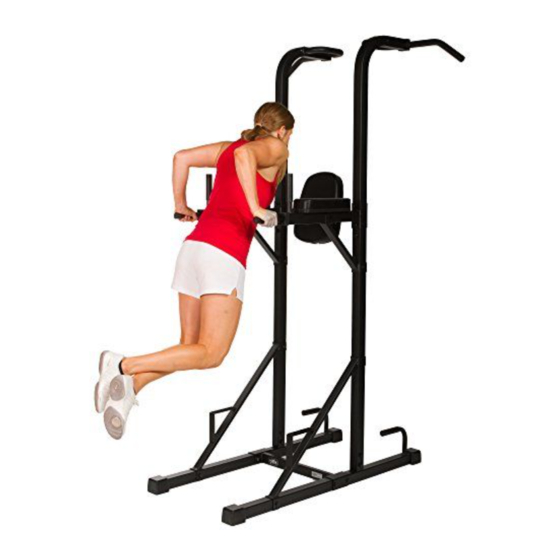
Summary of Contents for Mark Fitness XM-4451
- Page 1 XM-4451 POWER TOWER Owner’s Manual !CAUTION Read all precautions and instructions in this manual before using this equipment.
-
Page 2: Table Of Contents
Table of Contents Before You Start Important Safety Information Assembly 5-10 Parts List Exploded View... -
Page 3: Before You Start
CALL 1-800-719-4605 Monday-Friday 8:30 a.m.-5:00 p.m. XMARK FITNESS SERIES (Central Standard Time) MODEL: XM-4451 For Warranty information please visit www.xmarkfitness.com. When calling please have the following product information available: Model Name : XM-4451 Date Mfg.: Serial # Model Name Decal Location... -
Page 4: Important Safety Information
Important Safety Information Please read all instructions carefully before using this product. SAFETY TIPS Consult with your physician before engaging in any vigorous exercise. Know your heart rate and/or pulse as well as your physician-recommended heart rate training zone. Proper medical clearance is recommended for anyone beginning an exercise program especially if you are 35 years of age or older or suffer from heart or respiratory problems. -
Page 5: Assembly
Assembly Hardware Identifier See the drawings below to identify the hardware used in the assembly. The number in paren- theses is the reference number of the part. Note: Some hardware may be pre-installed in some parts. M10 Nylon Locknut (C1) M10 Washer (B1) M8 Washer (B2) M10 x 20mm Bolt (A1) - Page 6 Assembly Place the Bases (1) parallel to each other. Connect the Bottom Brace (9) to the Bases (1). Secure them with four M10x70 Bolts (A2) and four M10 Nylon Locknuts (C1), do not tighten the olts yet. Insert the two Lower Upright Tubes (6) into the Bases (1).
- Page 7 Assembly Insert the Lower Support Bars (4) between the Bases (1) and the Lower Upright Tubes (6). Secure them with four M10 x 70 Bolts (A2) and four Nylon Locknuts (C1). Push Right Pull-up Bar (2) into the Connective Head (17) on Upper Upright Tube (11), secure with one M10 x 55 Bolt (A3), one M10 Washer (B1).
- Page 8 Assembly Connect two Upper Upright Tubes (11) to the Lower Upright Tubes (6) and secure them using four M10 x 20 Bolts (A1) and four Washers D10 (B1). Do not tighten the olts yet. Attach the two Extend Arms (13) through the joints of the Upper and Lower Upright Tubes (11 &...
- Page 9 Assembly Connect the two Upper Support Bars (14) to both the Extend Arms (13) and the Lower Upright Tubes (6). Secure them using four M10 x 70 Bolts (A2), M10 Nylon Locknuts (C1). Do not tighten the olts yet. See steps 1-7. Tighten the M10 Nylon Locknuts (C1), M10 x 20 Bolts (A1) and M10 x 70 Bolts (A2) use in these steps.
- Page 10 Assembly Make sure that all parts are properly tightened before you use the Power Tower. Congratulations! You have completed assembly of your XM-4451!
-
Page 11: Parts List
Parts List XM-4451 Parts List Key NO DESCRIPTION BASE RIGHT PULL-UP BAR SHORT FOAM GRIP LOWER SUPPORT BAR 2" SQUARE SLEEVE LOWER UPRIGHT PROTECTIVE COVER ROUND PLUG, 25X1.5 BOTTOM CROSS BRACE ROUND INNER PLUG, 25x2 UPPER UPRIGHT TUBE UPPER CROSS BRACE... -
Page 12: Exploded View
Exploded View... - Page 13 Customer Service: 1-800-719-4605...


Need help?
Do you have a question about the XM-4451 and is the answer not in the manual?
Questions and answers