
Related Manuals for Waters 996


Summary of Contents for Waters 996
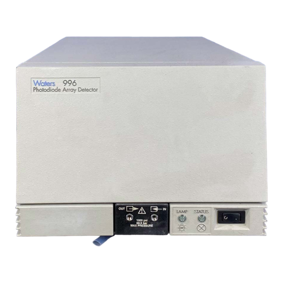
- Page 1 Waters 996 PDA Detector Operator’s Guide 34 Maple Street Milford, MA 01757 053021TP, Revision 0...
- Page 2 This manual is believed to be complete and accurate at the time of publication. In no event shall Waters Corporation be liable for incidental or consequential damages in connection with, or arising from, the use of this manual.
- Page 3 Attention: This is a highly sensitive instrument. Read this user's manual before using the instrument. STOP When you use the instrument, follow generally accepted procedures for quality control and methods development. If you observe a change in the retention of a particular compound, in the resolution between two compounds, or in peak shape, immediately take steps to determine the reason for the changes.
- Page 4 Le présent appareil numérique n’émet pas de bruits radioélectriques dépassant les limites applicables aux appareils numériques de la classe A prescrites dans les règlements sur le brouillage radioélectrique édictés par le Ministère des Communications du Canada. Symbols Used on the Waters 996 Photodiode Array Detector Direct current Alternating current...
-
Page 5: Table Of Contents
Table of Contents How to Use This Guide..............10 Chapter 1 Installation ..................14 1.1 Installation Site Requirements ..........14 1.2 Power Connections ............... 15 1.3 Millennium Workstation Connections......... 16 1.3.1 Connecting the IEEE-488 Cable........ 16 1.3.2 Setting the IEEE-488 Address ........18 1.4 Non-IEEE-488 Communication Connections ...... - Page 6 3.2.2 Removing the Lamp........... 41 3.3 Replacing the Fuses ............. 43 Chapter 4 Principles of the 996 PDA Detector Optics ........44 4.1 996 Detector Optics .............. 44 4.2 Resolving Spectral Data ............46 4.3 Measuring Light at the Photodiode ........47 4.4 Computing Absorbance Data Points ........
- Page 7 5.3 Spectral Contrast Angles ............57 5.4 Nonidealities ................. 60 5.4.1 Detector Noise ............60 5.4.2 Photometric Error ............61 5.4.3 Solvent Changes ............61 5.4.4 Threshold Angle............61 Appendix A Detector Specifications............... 63 Appendix B Spare Parts ................64 Appendix C Warranty Information ..............
- Page 8 Event Input/Output Terminal Strip..........22 Compression Screw Assembly ............24 996 Detector Indicator Lights............25 996 PDA Detector Indicator Lights ..........28 Flow Cell Access Door..............35 Removing the Flow Cell Assembly ..........35 Flow Cell and Fluidic Connections Assemblies ......36 Disassembling the Flow Cell............
- Page 9 Site Requirements ................ 14 Event In (Inject Start) Terminal Specifications on TTL or Switch Closure ..............21 Event Out Terminal Specifications on Contact Closure .... 21 996 Detector Troubleshooting ............28 Optics Assembly Components..........45 996 Detector Specifications............. 63 Spare Parts ................64 Warranty Periods..............
-
Page 10: How To Use This Guide
Audience This guide is intended for individuals who need to install, operate, maintain, and troubleshoot the Waters 996 PDA Detector. It is also intended for users who need to understand the Spectral Contrast principles underlying the processing of PDA detector data by Millennium software. - Page 11 Information Appendix D, Mobile Provides a table of absorbances at several wavelengths for Phase Absorbance common mobile phases. Related Documentation The table below lists other guides related to the Waters 996 PDA Detector Operator’s Guide . Title Description Millennium Online...
- Page 12 Adobe Acrobat Reader lets you easily print pages, pages ranges, or the entire electronic document by selecting Print from the File menu. For optimum print quantity, Waters recommends that you specify a Postscript printer driver for your printer. Ideally, use a printer that supports 600 dpi print resolution.
- Page 13 • Underlined, Blue Color text indicates hypertext cross-references to a specific chapter, section, subsection, or sidehead. Clicking this topic using the hand symbol automatically brings you to this topic within the electronic document. Right-clicking and selecting Go Back from the popup context menu brings you back to the originating topic.
-
Page 14: Chapter 1 Installation
Installation ® The Waters 996 Photodiode Array (PDA) Detector operates in any standard laboratory environment. The detector requires electrical power, sample and waste fluidic lines, and the Millennium® Workstation. Optional connections on the detector rear panel allow communication with chart recorders, data integrators, and other instruments that are not compatible with Millennium software control. -
Page 15: Power Connections
The Waters 996 PDA Detector is shipped with fuses rated for North American operation. If you operate the Waters 996 PDA Detector in another location, install the IEC-rated fuses (supplied in the Waters 996 Detector Startup Kit) in the fuse holder in the rear of the detector (refer to Section 3.3, Replacing the... -
Page 16: Millennium Workstation Connections
Connecting the Power Cord Connect one end of the 996 detector power cord to the rear panel power receptacle (Figure 1-2) and the other end to a power outlet. Power Cord Receptacle TP01452 Figure 1-2 Detector Rear Panel 1.3 Millennium... -
Page 17: Example Of Ieee-488 Cable Connections
Workstation: 1. Connect one end of the IEEE-488 cable to the IEEE-488 receptacle on the rear panel of the 996 detector. Connect the other end of the cable (stackable connector for daisy-chaining additional instruments) to the IEEE-488 connector on any of the other instruments in your chromatographic system (Figure 1-3). -
Page 18: Setting The Ieee-488 Address
IEEE-488 Cable Connection IEEE-488 Address Switches IEE 488 ADDRESS TP01457 Figure 1-4 Locating the IEEE-488 Address Switches 2. To instruct the 996 detector to accept the new IEEE-488 address, power off, then power on the detector (see Section 1.6, Startup/Shutdown). Installation... -
Page 19: Non-Ieee-488 Communication Connections
• Analog signal cables (from Startup Kit) Procedure To connect the Waters 996 detector to a device that receives analog output signals from the 996 detector 1. Pull off the Analog output terminal strip from the 996 detector rear panel (Figure 1-5). -
Page 20: Connecting Event Cables
If an inject start signal is not available over the IEEE-488 bus, you must provide a signal at an Event In terminal on the 996 detector rear panel. Manual injectors such as the Rheodyne 7725i provide a cable that connects the injector to an Event In terminal on the 996 detector rear panel. -
Page 21: Event In (Inject Start) Terminal Specifications On Ttl Or Switch Closure
The values of the event output signals generated by the 996 detector are specified by parameter values set from the Millennium Workstation. For details, refer to the “Waters 996 Detector Properties” topic in the Millennium Online Help Find tab. Electrical Specifications... -
Page 22: Fluidic Connections
Making Event Input/Output Connections To connect the 996 detector to an external event input or output device: 1. Pull off the Event Input/Output terminal strip from the rear panel (Figure 1-6). This simplifies the following steps. Removable Event Input/Output Terminal Strip... - Page 23 2. Cut the two lengths of tubing as follows: • Use a Waters 1/16-inch stainless steel tubing cutter or a file with a cutting edge to scribe the circumference of the tubing at the desired break point.
-
Page 24: Startup/Shutdown
To start up the 996 detector: 1. In your instrument method, set the solvent delivery system or pump to deliver 1 mL/min of degassed mobile phase. For details, refer to the “Waters 2690 Separations Module Properties” or the “Waters 600 Properties” topic in the Millennium Online Help Find tab. -
Page 25: Detector Indicator Lights
Chapter 2, Diagnostics and Calibration. WATERS 996 Photodiode Array Detector On/Off Switch Status Indicator Lamp Indicator TP01460 Figure 1-8 996 Detector Indicator Lights 5. Wait 1 hour for the deuterium lamp to stabilize before you attempt to acquire data at low absorbances. Startup/Shutdown... - Page 26 Shutdown To shut down the 996 detector: 1. If the mobile phase contains buffers, set the solvent delivery system or pump to deliver 1 mL/min of HPLC-grade water for 10 minutes. Otherwise, set the solvent delivery system or pump to deliver 1 mL/min of degassed methanol for 10 minutes.
-
Page 27: Diagnostics And Calibration
Section 2.1, Startup Diagnostics), contact Waters Technical Service at (800) 252-4752, U.S. and Canadian customers only . Other customers, call your local Waters subsidiary or your local Waters Technical Service Representative, or call Waters corporate headquarters for assistance at 1-508-478-2000 (U.S.). -
Page 28: Pda Detector Indicator Lights
Detector On/Off Switch Status Indicator Lamp Indicator TP01460 Figure 2-1 996 PDA Detector Indicator Lights Table 2-1 996 Detector Troubleshooting Symptom Possible Cause Corrective Action Status light off No power. 1. Check line cord connections. 2. Check outlet for power. - Page 29 Table 2-1 996 Detector Troubleshooting (Continued) Symptom Possible Cause Corrective Action Status light blinks and Failed startup Flush the flow cell (see Section 3.1.1, lamp light on diagnostics. Flushing the Flow Cell). Insufficient energy Flush the flow cell (see Section 3.1.1,...
-
Page 30: User-Initiated Diagnostics
These tests require connections to pump flow and/or test equipment. Note: You cannot perform diagnostics on a 996 detector while it is acquiring data. Note: The system administrator can restrict access to the 996 detector diagnostics by disabling user access to Quick Set. -
Page 31: Pda Calibration
Technical Service Representative, or call Waters corporate headquarters for assistance at 1-508-478-2000 (U.S.). 2.3 PDA Calibration You can adjust, or calibrate, the 996 detector to ensure that wavelength readings are accurate. Recalibrate the 996 detector only if the Wavelength Accuracy diagnostic (in the Internal Diagnostics tests) fails. - Page 32 To prepare for calibration: 1. Set the pump to deliver 1 mL/min of degassed methanol for 10 minutes. If methanol is not miscible with the previous solvent, flush with a miscible sovent before switching to methanol. 2. If you have been using buffers, flush with HPLC-quality water at 1 mL/min for 10 minutes, then switch to methanol for 10 minutes.
-
Page 33: Chapter 3 Maintenance
This chapter covers maintenance of the Waters 996 Photodiode Array Detector flow cell, lamp, and fuse. Caution: To avoid the possibility of electric shock, do not remove the 996 detector power supply covers. The power supply does not contain user-serviceable components. 3.1 Flow Cell Maintenance The flow cell requires maintenance when: •... -
Page 34: Removing The Flow Cell
Section 3.1.2, Removing the Flow Cell. 3.1.2 Removing the Flow Cell You do not need to shut down the 996 detector to remove and replace the flow cell. Note: Required Materials • 5/16-inch open-end wrench •... -
Page 35: Flow Cell Access Door
Flow Cell Access Door Thumbtabs TP01461 Figure 3-1 Flow Cell Access Door 6. Use the Phillips screwdriver to loosen the two thumbscrews that hold the flow cell assembly to the optics bench and the thumbscrew that secures the bracket holding the fluidic connections, then detach the bracket (Figure 3-2). -
Page 36: Disassembling And Cleaning The Flow Cell
3.1.3 Disassembling and Cleaning the Flow Cell The lens surface finish and the alignment of the lenses are critical to the performance of the 996 detector. Be careful not to touch or damage the lenses and the lens holders. Attention:... -
Page 37: Disassembling The Flow Cell
Required Materials • TORX T10 screwdriver • Small, flat-blade screwdriver • Lens tissue or nonparticulating swab • HPLC-grade methanol • Belleville spring washer • Flow cell gasket Procedure To disassemble and clean the flow cell (and lenses): 1. Use the TORX T10 screwdriver to remove the three screws that secure one of the lens holder assemblies (Figure 3-4). -
Page 38: Installing The Flow Cell Assembly
Attention: Solvents other than methanol may damage a disassembled flow cell. In normal use, the gasket protects the lens holder from solvents. STOP 3. Use a lens tissue or a nonparticulating swab to wipe the lens with methanol. 4. Remove and discard the gasket. 5. -
Page 39: Replacing The Lamp
Procedure To inspect the lamp usage indicator: 1. Power off the 996 detector, remove the power cord, and allow the lamp to cool for at least 15 minutes. 2. Lift up the front panel cover and pull it away from the chassis. -
Page 40: Lamp Access Door
Thumbtabs Lamp Access Door TP01461 Figure 3-5 Lamp Access Door 4. Examine the lamp usage indicator (Figure 3-6). Lamp Usage Indicator TP01466 Figure 3-6 Lamp Usage Indicator Maintenance... -
Page 41: Removing The Lamp
996 detector and disconnect the power cord. Procedure To replace the lamp in the 996 detector: 1. Power off the 996 detector, remove the power cord, and allow the lamp to cool for at least 15 minutes. Caution: To avoid the possibility of contacting hot surfaces, wait at least 15 minutes after powering off the detector before you handle the lamp. -
Page 42: Lamp Power Cord And Mounting Screws
10. Reconnect the lamp power connector (see Figure 3-7). 11. Close the lamp door and secure it with the thumbtab. 12. Install the front panel cover. 13. Reconnect the power cord and power on the 996 detector. Maintenance... -
Page 43: Replacing The Fuses
3.3 Replacing the Fuses Replace the fuses under the conditions indicated in the troubleshooting table (see Section Diagnostics). The 996 detector requires two 4 A, 250 V fuses (5 mm × 20 2.1, Startup mm). Caution: To avoid electrical hazards, power off the 996 detector and disconnect the power cord before you perform the following procedure. -
Page 44: Principles Of The 996 Pda Detector Optics
• 512 diodes • Optical resolution of 1.2 nm per diode • Operating wavelength range from 190 nm to 800 nm The light path through the optics assembly of the 996 detector is shown in Figure 4-1. Principles of the 996 PDA Detector Optics... -
Page 45: Optics Assembly Light Path
Lamp and Assembly Lamp Optics Figure 4-1 Optics Assembly Light Path Table 4-1 describes the optics assembly components in the 996 detector. Table 4-1 Optics Assembly Components Component Function Lamp and lamp Focuses light from the deuterium source lamp through a optics beamsplitter to the flow cell. -
Page 46: Resolving Spectral Data
The bandwidth of the light striking the photodiodes depends on the aperture width. The aperture width determines: • Attainable wavelength bandwidth at the photodiode array • Intensity of the light reaching the photodiode array (optical throughput) Principles of the 996 PDA Detector Optics... -
Page 47: Measuring Light At The Photodiode
Figure 4-2 Benzene Spectrum at 1.2 nm Resolution 4.3 Measuring Light at the Photodiode The Waters 996 Photodiode Array Detector measures the amount of light striking the photodiode array to determine the absorbance of the sample in the flow cell. -
Page 48: Photodiodes Discharged By Light
The interval between two readings of an individual diode is the exposure time. The 996 detector requires 11 msec to sequentially read all of the diodes in the array. The minimum exposure time is 11 msec. You can set exposure time from 11 to 500 msec. - Page 49 39 msec before beginning the recharge-and-reading sequence with diode 1. You set the exposure time parameter in the General tab of the 996 PDA Instrument Method Editor. You can specify either Auto Exposure or Exposure Time. For details, refer to the “Waters 996 PDA Detector Properties”...
-
Page 50: Computing Absorbance Data Points
Appendix D, Mobile Phase Absorbance). 4.4 Computing Absorbance Data Points The 996 detector calculates absorbance values before transmitting the data to the Millennium database. To calculate absorbance, the 996 detector: • Computes the absorbance at each diode using the dark current and reference spectrum (see Section 4.4.1, Calculating... -
Page 51: Absorbance As A Function Of Concentration
Photodiodes lose charge over time even when they are not exposed to light. The amount of charge lost is called dark current . At the start of a chromatographic run, the 996 detector closes the shutter to take a dark current reading for each diode. The shutter closes after the exposure time is calculated and stays closed for the same interval as the exposure time. -
Page 52: Resolution
Spectral resolution (or bandwidth) is the wavelength interval (in nanometers) between data points in an acquired spectrum. The minimal resolution of the 996 detector is 1.2 nm. Spectral resolution with the 996 detector is always a multiple of 1.2 nm. For example, the... -
Page 53: Filtering Data
Millennium Online Help Find tab. 4.4.3 Filtering Data Use the Channel 1 tab of the 996 PDA Instrument Method Editor (for details, refer to the “Waters 996 Detector Properties” topic in the Millennium Online Help Find tab) to apply an optional noise filter (the Filter Response parameter) to the data sent to the Millennium software database. -
Page 54: Spectral Contrast Theory
This chapter describes how Spectral Contrast represents absorbance spectra as vectors. When applied to the UV/Vis absorbance data collected by the 996 detector, the Spectral Contrast technique determines whether differences between spectra are due to the presence of multiple compounds in the same peaks (coelution) or due to nonideal conditions such as noise, photometric error, or solvent effects. -
Page 55: Representing Spectra As Vectors
A vector derived from the Waters 996 PDA Detector can include absorbances in any range between 190 nm and 800 nm with a spectral resolution of 1.2 nm. -
Page 56: Vectors Derived From Two Wavelengths
5.2.1 Vectors Derived from Two Wavelengths The Spectral Contrast algorithm uses vectors to characterize spectra (Figure 5-2). To understand the vector principle, consider two vectors (Figure 5-2) based on the spectra depicted in Figure 5-1. AU at 245 nm Figure 5-2 Plotting Vectors for Two Spectra The axes in Figure 5-2 are in absorbance units at the two wavelengths used to calculate... -
Page 57: Spectral Contrast Angles
To compare two spectra, the Spectral Contrast technique forms a vector for each spectrum in an n -dimensional space. The two spectral vectors are compared mathematically to compute the angle between the two vectors. Just as in the 2-wavelength comparison, a Spectral Contrast angle of zero in n -dimensional space means that all ratios of absorbances at corresponding wavelengths match. -
Page 58: Spectra With A Large Spectral Contrast Angle
Spectral Contrast Angle: 62.3° Compound B Compound A Wavelength (nm) Figure 5-3 Spectra with a Large Spectral Contrast Angle Spectra with Similar Shapes Figure 5-4, the absorbance spectra of two compounds, A and B, are similar, and therefore, have a small Spectral Contrast angle (3.0°). Spectral Contrast Theory... -
Page 59: Spectra With A Small Spectral Contrast Angle
Spectral Contrast Angle: 3.0° Compound A Compound B Wavelength (nm) Figure 5-4 Spectra with a Small Spectral Contrast Angle Differences Between Spectra of the Same Compound Small but significant differences between absorbance spectra can occur because of factors other than those due to the absorbance properties of different compounds. For example, multiple spectra of the same compound may exhibit slight differences because of detector noise, photometric error, high sample concentration, or variations in solvent conditions. -
Page 60: Nonidealities
Statistical and thermal variations add electrical noise to the absorbance measurements made by the 996 detector. The noise manifests itself as fluctuations in the baseline, known as baseline noise . The magnitude of any absorbance differences caused by statistical and thermal variations can be predicted from the instrument noise in the baseline region of a chromatogram. -
Page 61: Photometric Error
5.4.2 Photometric Error At high absorbances (generally greater than 1 AU), a combination of effects can produce slight departures (about 1%) from Beer’s Law due to photometric error. Although photometric errors at this level may have a negligible effect on quantitation, they can be a significant source of spectral inhomogeneity. -
Page 62: Effects Of Ph And Solvent Concentration On The Absorbance Spectrum Of P -Aminobenzoic Acid
Effect of pH Effect of pH p -Aminobenzoic Acid p - Aminobenzoic Acid pH 3.1 pH 5.1 pH 6.9 NH + COOH COOH COO– COOH pH 6.9 pH 5.1 pH 3.1 Effect of Acetonitrile Concentration Effect of Acetonitrile Concentration p -Aminobenzoic Acid p - Aminobenzoic Acid COOH 2–10% Acetonitrile... -
Page 63: Detector Specifications
Appendix A Detector Specifications Table A-1 lists the Waters 996 PDA Detector specifications. Table A-1 996 Detector Specifications Item Specification 11.5 × 22 inches (29 × 56 cm) Dimensions Weight 31 lbs (14.3 kg) Wavelength range 190 to 800 nm Wavelength accuracy ±1 nm... -
Page 64: Appendix B Spare Parts
Appendix B Spare Parts The spare parts listed in Table B-1 are those parts recommended for customer installation. Damage incurred by performing unauthorized work on your 996 detector may invalidate certain warranties. Table B-1 Spare Parts Item Part Number Flow cell, standard... -
Page 65: Appendix C Warranty Information
The foregoing warranty does not apply to any material deviation from the Specifications by any component of the Waters 996 PDA Detector that results from (a) use of the Waters 996 PDA Detector for any purpose other than general purpose use and specifically... - Page 66 Exclusive Remedy In the event of any failure of the Waters 996 PDA Detector to perform, in any material respect, in accordance with the warranty set forth herein, the only liability of Waters Corporation to Customer, and Customer’s sole and exclusive remedy, shall be the use, by Waters Corporation, of commercially reasonable efforts to correct for such deviations, in Waters Corporation’s sole discretion, replacement of the purchased Waters 996 PDA...
- Page 67 Warranty Service Warranty service is performed at no charge and at Waters’ option in one of three ways: • A service representative is dispatched to the customer facility. • The product is repaired at a Waters repair facility. • Replacement parts with appropriate installation instructions are sent to the customer.
-
Page 68: Warranty Periods
1 year Deuterium lamp 1000 hours Gaskets warranted Windows items Lenses Fuses Plunger seals Tubing and fittings Lamp Replacement Warranty The Waters 996 PDA Detector deuterium lamp is warranted to light and pass powerup verification tests for 1000 hours. Appendix C... -
Page 69: Shipments, Damages, Claims, And Returns
This request must be made within 15 days of receipt. Otherwise, the claim will not be honored by the carrier. Do not return damaged goods to the factory without first securing an inspection report and contacting Waters for a return merchandise authorization number (RMA). -
Page 70: Appendix D Mobile Phase Absorbance
Appendix D Mobile Phase Absorbance This appendix provides a list of the absorbances at several wavelengths for commonly used mobile phases. Choose your mobile phase carefully to reduce baseline noise. The best mobile phase for your application is one that is transparent at the chosen detection wavelengths. - Page 71 Table D-1 Mobile Phase Absorbance Measured Against Air or Water (Continued) Absorbance at Specified Wavelength (nm) Acids and Bases Acetic acid, 1% 2.61 2.63 2.61 2.43 2.17 0.87 0.14 0.01 <0.01 — Hydrochloric 0.11 0.02 <0.01 — — — — —...
- Page 72 Table D-1 Mobile Phase Absorbance Measured Against Air or Water (Continued) Absorbance at Specified Wavelength (nm) Potassium 0.03 <0.01 — — — — — — — — phosphate, monobasic 10 mM Potassium 0.53 0.16 0.05 0.01 <0.01 — — — —...
- Page 73 Table D-1 Mobile Phase Absorbance Measured Against Air or Water (Continued) Absorbance at Specified Wavelength (nm) Waters PIC Reagents PIC A, 1 vial/L 0.67 0.29 0.13 0.05 0.03 0.02 0.02 0.02 0.02 <0.01 PIC B6, 1 vial/L 2.46 2.50 2.42 2.25...
-
Page 74: Index
Damage, warranty maximum Dark current mobile phase Data acquisition photometric error Auto Exposure parameter solvent change effects Exposure Time parameter Waters 996 calculations Derived vectors Acquisition Diagnostics Auto Exposure parameter DIP switch, setting Exposure Time parameter Address, setting Analog output specifications... - Page 75 Fuses Mobile phase IEC-rated absorbances maintenance wavelengths replacement Network address IEC-rated fuses Noise effects IEEE-488 address, setting Nonidealities Inputs Non-IEEE-488 connections Installation electrical fluidic site selection Outputs Instrument method Auto Exposure parameter Exposure Time parameter Parts, spare Photodiode array Photometric error Lamp Power connections hardware theory...
- Page 76 – Spectrum match, spectral shape photodiode array overview differences reference spectrum spare parts Start up, procedure specifications spectral resolution Waters liability Waters Technical Service, contacting Terminal strip Wavelength connections accuracy diagram derived vectors Threshold angle mobile phase absorbances Troubleshooting –...
Need help?
Do you have a question about the 996 and is the answer not in the manual?
Questions and answers