
Related Manuals for Fluke 80i-110s


Summary of Contents for Fluke 80i-110s
- Page 1 Table of Contents 80i-110s AC/DC CURRENT PROBE Users Manual November 1996 ¤ 1994, 1996 Fluke Corporation. All rights reserved. All product names are trademarks of their respective companies. Printed in the Netherlands ®...
-
Page 3: Table Of Contents
Table of Contents Table of Contents INTRODUCING THE CURRENT PROBE ......3 UNPACKING ..........4 INSTALLING THE BATTERY . -
Page 5: Introducing The Current Probe
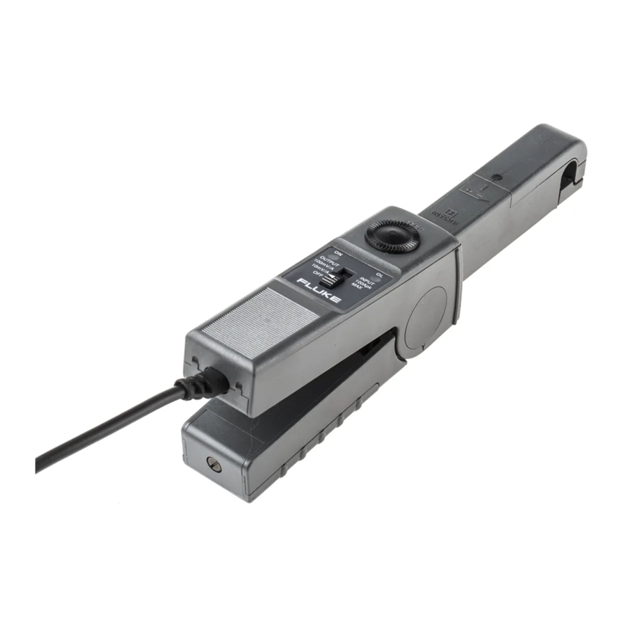
The probe's performance is optimized for accurate reproduction of currents at line frequency and up to the 50th harmonic waveform. The 80i-110s is also compatible with any instrument capable of millivolt measurements. The Current Probe (shown in Figure 1) provides the following benefits: •... -
Page 6: Unpacking
Quick Reference Card • 9 volt Battery, type IEC 6LR61 Check the contents of the shipping box for completeness. If something in the box has been damaged or missing, contact your distributor or the nearest FLUKE sales or service office immediately. -
Page 7: Installing The Battery
80i-110s Instruction Manual INSTALLING THE BATTERY WARNING TO AVOID ELECTRICAL SHOCK, UNCLAMP THE CURRENT PROBE FROM ANY CONDUCTOR, AND DISCONNECT THE SCOPEMETER TEST TOOL OR ANY OTHER MEASUREMENT DEVICE BEFORE INSTALLING OR REPLACING THE BATTERY. At first use, remember to install the battery. Referring to Figure 2, use the following procedure to install the battery: 1. -
Page 8: Using The Current Probe Safely
Earth Recycling Conformité Européenne The 80i-110s is designed to meet the requirements of IEC Publication 1010 and oth- er safety standards (see "Safety Specifications"). Follow all warnings to ensure safe operation. Use of this equipment in a manner not specified herein may impair the protection... -
Page 9: Electrical Specifications
80i-110s Instruction Manual ELECTRICAL SPECIFICATIONS All Electrical Specifications are valid at a temperature of 23 qC r3 qC (73 qF r5 qF). Current Ranges: 0 to 10A dc or ac peak 0 to 100A dc or ac peak Output Signals:... - Page 10 80i-110s Instruction Manual Input Load Impedance (of host instrument): >1 M: in parallel with up to 100 pF. Useful Bandwidth (-3 dB): 0 to 100 kHz Rise or Fall Time: <4 Psec. Output noise level: typ. 480 PV pk-pk 10 mV/A 100 mV/A typ.
-
Page 11: General Specifications
80i-110s Instruction Manual GENERAL SPECIFICATIONS Dimensions: 67 x 231 x 36 mm (2.6 x 9.1 x 1.4 inches) Weight: 330g (11.6 oz.), battery included Output Cable: 1.6 meters (63 inches) Maximum Conductor Size: ‡ 11.8 mm (.46 inch) Maximum Jaw Opening: 12.5 mm (.49 inch) -
Page 12: Safety Specifications
80i-110s Instruction Manual SAFETY SPECIFICATIONS Designed to meet the requirements of IEC 1010 and CSA-C22.2 No. 1010.1: Installation Category II, Working Voltage 600V, Pollution Degree 2, Installation Category III, Working Voltage 300V, Pollution Degree 2 Installation (Overvoltage ) Category II refers to local level, appliances, and portable equipment. -
Page 13: Instrument Compatibility
80i-110s Instruction Manual INSTRUMENT COMPATIBILITY The 80i-110s is compatible with any Fluke ScopeMeter test tool, Power Harmonics Analyzer, Oscilloscope, Multimeter, or other voltage measurement device that has the following features: • BNC input connector. A BNC-to-banana adapter (order PM9081/001 from Fluke) can also be used with standard inputs on a digital multimeter (DMM). -
Page 14: Using The Current Probe
USING THE CURRENT PROBE To use the Current Probe, follow these instructions: 1. Connect the 80i-110s Current Probe to the desired input on the measuring instrument. When the ScopeMeter test tool or an oscilloscope is used, it must have DC coupled input. When you are using a digital multimeter, use the BNC- to-banana adapter (PM9081/001) to connect the probe to the input. - Page 15 80i-110s Instruction Manual 6. Observe the current value or waveform on your display or the current value readout on the multimeter. 7. On the ScopeMeter test tool, adjust the vertical range knob and time division knob for the best display.
-
Page 16: Measurement Considerations
80i-110s Instruction Manual MEASUREMENT CONSIDERATIONS Observe the following guidelines for positioning the Current Probe Jaws: • Center the conductor inside the probe jaws. • Make sure the probe is perpendicular to the conductor. • Make sure that the arrow marked on the jaw of the Current Probe points toward the correct direction. -
Page 17: Maintenance
AT THE BEGINNING OF THIS USERS MANUAL BEFORE PROCEEDING. Repairs or servicing not covered in this Users Manual should be performed only at a Fluke Service Center. A probe under warranty will be promptly repaired or replaced (at Fluke's discretion) and returned at no charge. -
Page 18: Performance Verification
80i-110s Instruction Manual PERFORMANCE VERIFICATION Verify probe accuracy with the test setups shown in Figure 5. Required test equipment is defined in Table 1. Toroid coil construction is illustrated in Figure 6. Do the following to verify the probe accuracy: 1. - Page 19 80i-110s Instruction Manual Figure 5. Performance Test and Calibration Setup...
- Page 20 80i-110s Instruction Manual Figure 6. Toroid Coil Construction Table 2. Performance Test Points (5100B Direct) Current range 0 to 10A DC Measurement: 5100B DC AMPS LOW LIMIT HIGH LIMIT SETTINGS MEASURED OUTPUT OUTPUT 0.1A 92 mV 108 mV 0.5A 480 mV 520 mV 0.9A...
- Page 21 80i-110s Instruction Manual AC Measurement: 5100B RMS AMPS LOW LIMIT HIGH LIMIT SETTINGS MEASURED OUTPUT OUTPUT 0.1A, 60 Hz 92 mV 108 mV 0.3A, 400 Hz 286 mV 314 mV 0.5A, 2 kHz 465 mV 535 mV 0.6A, 4 kHz...
-
Page 22: Replacement Parts
80i-110s Instruction Manual IF YOUR CURRENT PROBE DOES NOT WORK If the 80i-110s does not perform properly, use the following steps to help isolate the problem: 1. Test the battery: be sure that the green ON-indicator lights when you select the 10 mV/A range or the 100 mV/A range.
Need help?
Do you have a question about the 80i-110s and is the answer not in the manual?
Questions and answers