
Subscribe to Our Youtube Channel
Related Manuals for M2 Antenna Systems SYSTEM SAMPLE 3


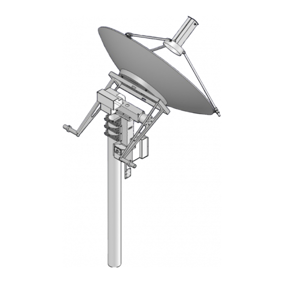
Summary of Contents for M2 Antenna Systems SYSTEM SAMPLE 3
- Page 1 M2 Antenna Systems, Inc. SYSTEM SAMPLE 3 Model No: 2 AXIS WITH L-BAND FEED M2 Antenna Systems, Inc. 4402 N. Selland Ave. Fresno, CA 93722 Tel: (559) 432-8873 Fax: (559) 432-3059 Web: www.m2inc.com 05/19/09 ©2009 M2 Antenna Systems Incorporated Rev.00...
-
Page 2: Assembly Manual
ASSEMBLY MANUAL BEFORE YOU BEGIN: Look over all the DRAWINGS to get familiar with the various parts and assem- blies in the system. Tools handy for assembly process: screwdriver, 11/32, 7/16, 1/2, 9/16 and 5/8” spin-tites, end wrenches and/or sockets, measuring tape. Note: All installations are unique in some way, which means it's OK to preassemble certain hardware, or rearrange the assembly process to meet specific site requirements. - Page 3 ASSEMBLY MANUAL 1. Install EL-1000 assembly to AZ-1000 assembly. Note: Timing mark on EL-1000 gear spacer protruding from cover. This mark represents EL system at 90 degrees. This will help you align counter balance arms properly.
- Page 4 ASSEMBLY MANUAL Note: With counter balance arm in this position, the dish would be mounted at 90 degrees, pointing straight up. 1. Add C-Balance Arm, align with all six holes and insert hardware as shown above. 2. Add C-Balance Spacer. Make sure all six bolt holes line-up.
- Page 5 ASSEMBLY MANUAL 1. Install Dish Mount Box Frame Assembly.
- Page 6 ASSEMBLY MANUAL 1. Prepare dish for installation. Begin by installing Feed Leg Foot Bracket on dish as shown in Detail A. 1. Pre-assemble Feed Leg Adjuster Assemblies, (Qty. 3).
- Page 7 ASSEMBLY MANUAL 1. Install Feed Leg Adjuster Assembly to Feed Leg Foot. 1. Install Dish to Dish Mount Box Frame Assembly.
- Page 8 ASSEMBLY MANUAL 1. Install Dish Feed Legs. Line up holes as shown in detail C. 2. Secure Dish Feed Legs. Repeat this step for the other two remaining legs. 3. Install feed assembly as shown. Check all hardware for tightness and inspect your work.
- Page 9 ASSEMBLY MANUAL 1. Install Cable Route Flag Assembly. 1. Install C-Balance locking collars with proper weights as desired to help counter balance the system.
- Page 10 PARTS & HARDWARE DESCRIPTION AZ-1000 Assembly..................1 EL-1000 Assembly ..................1 Box Frame Assembly ................... 1 C-Balance Arm..................... 2 Feed Leg ...................... 3 Feed Leg, Foot..................... 3 Feed Leg, Slide Clamp................. 3 Feed Leg, Clamp Cap .................. 3 6” Pipe Clamp #1 ..................3 6”...
-
Page 11: Parts & Hardware
Screw, 6-32 x 1/2” Pan Head Phil S.S............12 Lock Nut, 6-32 S.S..................12 Allen Key, 5/64”................... 1 Carefully manufactured by: M2 Antenna Systems, Inc. 4402 N. Selland Ave. Fresno, CA 93722 (559) 432-8873 Fax (559) 432-3059 Web: www.m2inc.com... - Page 12 5 PIN CONNECTOR WIRE DETAIL 1. Route cable thru connector assembly as shown above. Note: Connector picture taken from back shell of right angle connector. 2. Match colors and letters and solder wires to con- nector pins as shown above. Use supplied shrink tubing (3/4”...
- Page 13 MAINTENANCE & SPARE PARTS LIST 90 day maintenance 1. Visual inspection of complete system, look for rust or corrosion and loose hardware. 2. Manually move each axis individually and LISTEN for smooth operation. 3. Check cables for wear and cracking. 4.
-
Page 14: Troubleshooting
TROUBLESHOOTING Troubleshooting 1. Motors not moving. A. Check for voltage coming out of control box. B. Check for voltage at motor (AZ / EL=42 VDC POL=26 VDC). C. Check all wiring from control box to motor. D. Check motor for binding. 2. - Page 15 WORM & WORMGEAR ADJUSTMENT Excessive backlash may develop after using system for some time. We have incorporated a built in backlash adjustment block to keep backlash at a minimum. Please review drawings shown for more detailed information. To adjust system: 1.
-
Page 16: Warranty Information
M2 is responsible for charges (in the United States) to return the repaired / replacement product only where warranty service is involved. M2 Antenna Systems, Inc. 4402 N. Selland Ave. Fresno, CA 93722 (559) 432-8873 Fax (559) 432-3059 Web: www.m2inc.com...
Need help?
Do you have a question about the SYSTEM SAMPLE 3 and is the answer not in the manual?
Questions and answers