Advertisement
SPECIFICATIONS:
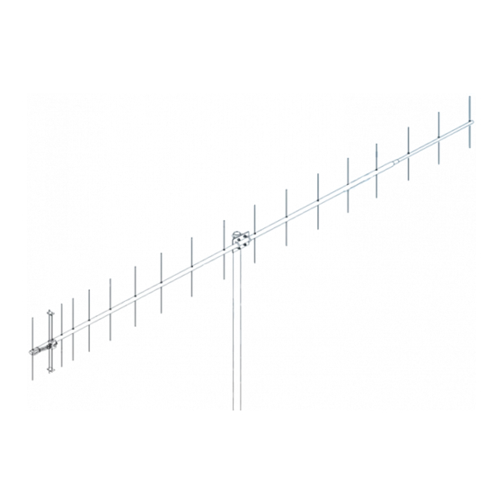
Model ......................................... 440-18
Frequency Range ....................... 420 To 453 MHz
*Gain .......................................... 16.64 dBi
Front to back .............................. 23 dB Typical
Beamwidth ............................... E=27° H=32°
Feed type ................................... Folded Dipole
Feed Impedance. ....................... 50 Ohms Unbalanced
Maximum VSWR ........................ 1.2:1 Typical
Input Connector .......................... "N" Female
FEATURES:
The 440-18 is a computer optimized broadband yagi featuring an excellent pattern and good gain across its band-
width. It can be mounted vertically or horizontally and is ideal for stacking two or more for additional gain. Its light weight
yet sturdy construction keep the cost low and the performance high. Use it for ATV, OSCAR, FM, LONG HAUL TROPO,
ETC. We guarantee you will be impressed.
The heart of the 440-18 is a unique Driven Element Module with superior weather resistance and power handling
abilities. All connectors are O-ring sealed to the CNC machined block and internal connections are sealed in a space-
age silicone gel with a dielectric strength nearly 4 times greater than air. The Balun coax connectors are triple O-ring
sealed. Other key mechanical and electrical parts are CNC machined from 6061-T6 aluminum and all hardware except U-
bolts is stainless steel.
The 440-18 offers you uncompromising performance, enduring mechanical construction, and long term electrical
integrity. Where else but M
M2 Antenna Systems, Inc. 4402 N. Selland Ave. Fresno, CA 93722
M2 Antenna Systems, Inc.
Model No: 440-18
*Subtract 2.14 from dBi for dBd
2
.
Tel: (559) 432-8873 Fax: (559) 432-3059 Web: www.m2inc.com
©2015 M2 Antenna Systems Incorporated
Power Handling .......................... 1.5 kW
Boom Length / Dia ...................... 137"' / 1" To 3/4"
Maximum Element Length .......... 14"
Turning Radius: .......................... 69'
Stacking Distance ....................... 51" High & 52" Wide
Mast Size .................................... 2"
Wind area / Survival ................... 0.68 Sq. Ft. / 100 MPH
Weight / Ship Wt. ........................ 5 Lbs. / 7 Lbs.
06/09/15
Rev.03
Advertisement
Table of Contents

Related Manuals for M2 Antenna Systems 440-18


Summary of Contents for M2 Antenna Systems 440-18
-
Page 1: Specifications
FEATURES: The 440-18 is a computer optimized broadband yagi featuring an excellent pattern and good gain across its band- width. It can be mounted vertically or horizontally and is ideal for stacking two or more for additional gain. Its light weight yet sturdy construction keep the cost low and the performance high. - Page 2 440-18 ASSEMBLY MANUAL 1. Start by laying out the boom sections using the DIMENSION sheet as a guide. Use 8-32 X 1-1/4 screws and locknuts to join sections. Sections may be swaged to fit each other or use short internal splice sections.
- Page 3 Keeping metallic masts, crossbooms and the feed coax out of the element plane will help maintain good VSWR and pattern. FOR HORIZONTAL POLARIZATION, the 440-18 may be mounted to a metallic vertical mast or a horizontal NON-METALLIC crossboom (no conductive material in element plane). If mounted to a horizontal crossboom, route the feedline forward to the boom-to-mast plate, loop down, and bring back to crossboom at least 6”...
- Page 4 440-18 DIMENSION SHEET...
- Page 5 440-18 PARTS & HARDWARE DESCRIPTION BOOM SECTION, 1 X .058 X 57” SOE ..... 1 BOOM SECTION, 1 X .058 X 60” SOE ..... 1 BOOM SECTION, 3/4 X .058 X 25-1/2” .... 1 ELEMENTS, 3/16 ROD x Dimension Sheet ..18 DRIVEN ELEMENT BLOCK ......
Need help?
Do you have a question about the 440-18 and is the answer not in the manual?
Questions and answers