Advertisement
SPECIFICATIONS:
Model ......................................... 2M18XXX
Frequency Range ....................... 144 To 146 MHz
*Gain for 1 / 2 / 4 ........................ 17.14 / 20.14 / 23.14 dBi
Front to back .............................. 26 dB Typical
Beamwidth ............................... E=26° H=28°
Feed type ................................... "T" Match
Feed Impedance. ....................... 50 Ohms Unbalanced
Maximum VSWR ........................ 1.2:1
Input Connector .......................... "N" Female
FEATURES:
The 2M18XXX has been extensively used by many moonbouncers and other weak signal enthusiasts for
the last eight years. The clean, sharp pattern yields a very good G/T (gain/temperature in K) which, in everyday
language, means you hear more signal and less noise. It is ideal as a single antenna or in stacked arrays of 24 or
more antennas, yielding a full 6 dB of stacking gain for four antennas! Mechanically, the boom is strong in the mid-
dle and tapered in 1/4" steps to reduce weight and wind area. M
with the unique driven element module. The aluminum CNC machined housing features "O" ring seals on all three
connectors and internal connections are potted in silicon gel than enhances the power handling capability. That is
important to those who feel life is too short for QRP (Low power)! All hardware is stainless except the U-bolts. By all
standards the "18XXX" is a true thoroughbred among VHF antennas!
M2 Antenna Systems, Inc. 4402 N. Selland Ave. Fresno, CA 93722
M2 Antenna Systems, Inc.
Model No: 2M18XXX
*Subtract 2.14 from dBi for dBd
Tel: (559) 432-8873 Fax: (559) 432-3059 Web: www.m2inc.com
©2015 M2 Antenna Systems Incoporated
Power Handling .......................... 1.5 kW
Boom Length / Dia ...................... 36.5' / 1-1/2" to 3/4"
Maximum Element Length .......... 41"
Turning Radius: .......................... 19' 6"
Stacking Distance ....................... 14' High & 14.5' Wide
Mast Size .................................... 2" Nom.
Wind area / Survival ................... 2.9 Sq. Ft. / ?? MPH
Weight / Ship Wt. ........................ 14 Lbs. / 16 Lbs.
2
has integrated the computer optimized design
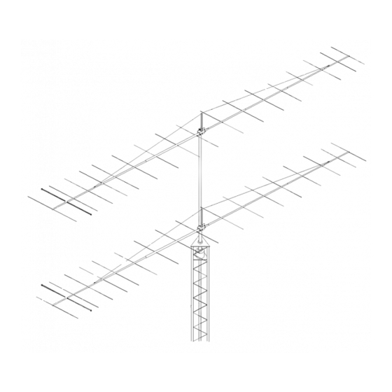
Gain for single antenna
Gain for two atennas
stacked vertically as pictured
Gain for 4 antennas
stacked 2 x 2
05/26/15
Rev.00
Advertisement
Table of Contents

Related Manuals for M2 Antenna Systems 2M18 series


Summary of Contents for M2 Antenna Systems 2M18 series
-
Page 1: Specifications
QRP (Low power)! All hardware is stainless except the U-bolts. By all standards the “18XXX” is a true thoroughbred among VHF antennas! M2 Antenna Systems, Inc. 4402 N. Selland Ave. Fresno, CA 93722 Tel: (559) 432-8873 Fax: (559) 432-3059 Web: www.m2inc.com 05/26/15 ©2015 M2 Antenna Systems Incoporated... - Page 2 2M18XXX ASSEMBLY MANUAL TOOL REQUIRED: Flat blade screwdriver, 11/32 nut driver or socket, 7/16 and 1/2 end wrenches and / or sockets, measuring tape. Start by laying out the boom sections using the DIMENSION sheet as a guide. Use 8-32 X 1- 1/4 screws and locknuts to join 3/4”...
- Page 3 2M18XXX ASSEMBLY MANUAL Slide the bars onto the 3/16” rod driven element tips and the 1/4” Driven Element Block Rods Position the Shorting Bars as per the DIMENSION SHEET. Then align the bars and rods with each other and tighten the setscrews. 9.
- Page 4 2M18XXX DIMENSION SHEET...
- Page 5 2M18XXX ASSEMBLY DETAILS...
- Page 6 2M18XXX PARTS & HARDWARE BOOM SECTION, 1-1/2 X .058 X 60” SOE ..2 BOOM SECTION, 1-1/2 X .058 X 60” SBE ..1 BOOM SECTION, 1-1/4 X .058 X 60” SOE ..1 BOOM SECTION, 1-1/4 X .058 X 60” SOE ..1 BOOM SECTION, 1 X .058 X 60”...
Need help?
Do you have a question about the 2M18 series and is the answer not in the manual?
Questions and answers