Advertisement
Quick Links
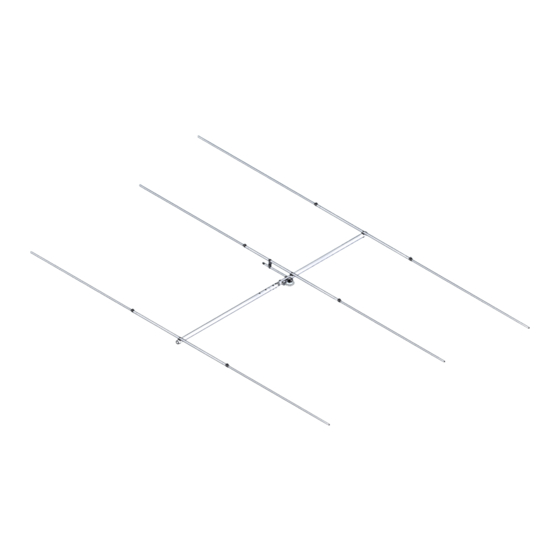
SPECIFICATIONS:
Model .............................6M-3SS
Frequency Range ................ 50.0 To 54.0 MHz Tunable
*Gain ................................... 8.1 dBi
Front to back ....................... 28 dB Typical
Beamwidth ........................ E=64° H=96°
Feed type ............................ Gamma Match
Feed Impedance. ................ 50 Ohms Unbalanced
Maximum VSWR ................. 1.5:1
Input Connector ................... SO-239
FEATURES:
New licensed Hams will find the 6M-3SS a low cost, medium performance antenna to be a
great choice for a starter antenna without compromising quality. A single heavy duty mounting cradle
and stainless steel hardware, give you the confidence of quality construction you have come to ex-
pect from M2. Built with size and portability in mind, this antenna is great for Field Days, Mountain
Topping, Fox Hunts and DXpedition use. The antenna breaks down to no more than 40" long, making
it a natural for trips.
M2 Antenna Systems, Inc. 4402 N. Selland Ave. Fresno, CA 93722
M2 Antenna Systems, Inc.
Model No: 6M-3SS
*Subtract 2.14 from dBi for dBd
Tel: (559) 432-8873 Fax: (559) 432-3059 Web: www.m2inc.com
©2015 M2 Antenna Systems Incoporated
Power Handling .......................... 0.5 kW
Boom Length / Dia ...................... 5' 8" / 1"
Maximum Element Length .......... 123"
Turning Radius: .......................... 5' 5"
Stacking Distance ....................... 14' High & 18' Wide
Mast Size .................................... 1-1/2" to 2" Nom.
Wind area / Survival ................... 0.7Sq. Ft. / 75 MPH
Weight / Ship Wt. ........................ 6 Lbs. / 7 Lbs.
02/27/15
Rev.05
Advertisement

Related Manuals for M2 Antenna Systems 6M-3SS


Summary of Contents for M2 Antenna Systems 6M-3SS
-
Page 1: Specifications
*Subtract 2.14 from dBi for dBd FEATURES: New licensed Hams will find the 6M-3SS a low cost, medium performance antenna to be a great choice for a starter antenna without compromising quality. A single heavy duty mounting cradle and stainless steel hardware, give you the confidence of quality construction you have come to ex- pect from M2. - Page 2 6M-3SS ASSEMBLY MANUAL Congratulations on your purchase of the 6M-3SS, You have chosen a versatile 6M antenna, it can be tuned for all modes of communication in the 6M band. This versatile antenna can break down into a small package so you can use it for field days or DXpeditions, making this antenna a good choice. We have offered (4) tuning choices, 50.150 MHZ used primarily on Horizontal polarity on SSB, 51.00 MHZ, 52.00 MHZ, and 53.00...
- Page 3 6M-3SS ASSEMBLY MANUAL Tools handy for assembly process: Phillips head screwdriver,11/32” nut driver or socket, 7/16” end wrenches / sockets, measuring tape. *We have supplied a small container of zinc paste with the hardware. It is best to apply a small amount of this zinc paste to each aluminum to aluminum connection to help slow down the oxidation process and for the best electrical connection.
- Page 4 6M-3SS ASSEMBLY MANUAL 12. Install the two halves of the Shorting Bar onto the Gamma Tube and the driven element below. Refer to the TUNING CHART for proper location of the shorting bar. Tighten the shorting bar in place using a single 8-32 x 7/8” screw and lock nut.
- Page 5 6M-3SS DIMENSION SHEET SPACING BOTTOM VIEW 1” “A” DIM “A” DIM YOUR CHOICE————— YOUR CHOICE————— REFLECTOR COMPRESSION CLAMP DRIVEN ELEMENT YOUR CHOICE————— YOUR CHOICE————— “C” DIM “B” DIM 28 1/16” THE GAMMA CONNECTOR BLOCK MOUNTS IN THE HOLE FORWARD YOUR CHOICE—————-...
- Page 6 6M-3SS ASSEMBLY DETAILS 1/2” x 36”...
- Page 7 6M-3SS PARTS & HARDWARE DESCRIPTION…………………………………………………..QTY BOOM SECTION, 1 X .058 X 36” SOE ........1 BOOM SECTION, 1 X .058 X 37” ........... 1 ELEMENT SECTION, 1/2 X .049 X 36” ........3 ELEMENTS, 3/8 X .049 X SEE DIM SHEET ......6 GAMMA CONNECTOR BLOCK ASSEMBLY ......
Need help?
Do you have a question about the 6M-3SS and is the answer not in the manual?
Questions and answers