Table of Contents
Advertisement
Quick Links
Advertisement
Table of Contents

Related Manuals for SystemAir SPLIT-AHU Kit 0-10V LNS


Summary of Contents for SystemAir SPLIT-AHU Kit 0-10V LNS
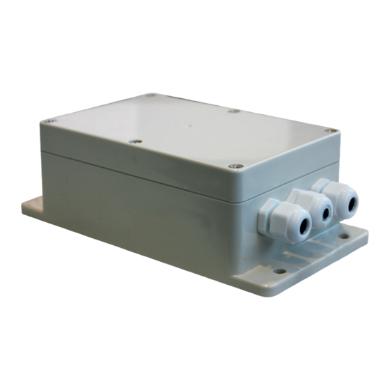
- Page 1 SPLIT-AHU Kit 0-10V LNS Installation and Operating Manual...
-
Page 2: Safety Instructions
Installation and Operating Manual 1. SAFETY INSTRUCTIONS Read this manual carefully. • This manual contains important information for correct using of this device. • The manufacturer reserves the right to change the technical characteri- stics and specification of its products without notice. WARNING For repair or maintenance please order an authorised service technician. - Page 3 This symbol mark is valid only for EU countries. » This symbol complies with directive 2002/96/EG article » This Systemair product is built with high-quality materials » and components which can be recycled or reused. This symbol indicates that electrical and electronic »...
- Page 4 Installation and Operating Manual 3. INTRODUCTION The SPLIT-AHU Kit 0-10V LNS control module enables to control Single- or Multisplit outdoor units with L, N, S communication. It allows to control outdoor unit capacity as well as operation mode (heating or cooling) of an air handling unit or a DX coil.
-
Page 5: System Design
Installation and Operating Manual 5. SYSTEM DESIGN Single-Split Depending on the Outdoor Unit used, up to 5 Indoor Units can be connected. Power supply Power supply SPLIT-AHU Kit LNS communication with 0-10V LNS outdoor unit REFRIGERANT PIPES T2 SENSOR... - Page 6 Installation and Operating Manual Multi-Split Depending on the Outdoor Unit used, up to 5 Indoor Units can be connected. Power supply Power supply SPLIT-AHU Kit LNS communication with 0-10V LNS outdoor unit T2 SENSOR Air Handling Unit 1 Power supply SPLIT-AHU Kit LNS communication with 0-10V LNS...
- Page 7 Installation and Operating Manual Multi-Split Depending on the Outdoor Unit used, up to 5 Indoor Units can be connected Power supply Power supply SPLIT-AHU Kit LNS communication with outdoor unit 0-10V LNS T2 SENSOR Air Handling Unit LNS communication with indoor unit REFRIGERANT PIPES Indoor unit for SYSPLIT MULTI...
-
Page 8: Function And Setting
(between Outdoor Unit and SPLIT-AHU Kit 0-10V LNS) LIYY Communication Line 10 x 0,25 mm² (between Air Handling Unit and SPLIT-AHU Kit 0-10V LNS) LIYY NOTE » Cable selection in accordance with the local regulations. » No low-voltage conductors and high-voltage conductors together in one... - Page 9 Installation and Operating Manual Connection Terminal Introduction: L, N, S Power supply and communication with outdoor unit connection terminal 230 V, 1-phase, 50/60 Hz. ALARM Digital output 5A - 250 VAC or 5A-30 VDC. When outdoor unit has malfunction signal is activated. DEFROST Digital output 5A - 250 VAC or 5A-30 VDC.
- Page 10 10 I Installation and Operating Manual ENC1 Knob for multi split connection to select indoor unit capacity. This knob is for multi indoor units connection only. This knob will not work at one indoor to one outdoor connection. Knob selection Indoor unit capacity Reference Code (Indoor unit)* 2,0 kW unit...
-
Page 11: Technical Features
11 I Installation and Operating Manual 7. TECHNICAL FEATURES Model MULTI2 18 MULTI3 27 MULTI4 36 MULTI5 42 SYSPLIT EVO32 HP Q EVO32 HP Q EVO32 HP Q EVO32 HP Q Art. no. Outdoor unit 315813 315814 315864 315865 Refrigerant/Charged quantity kg R32 / 1,3 R32 / 1,57 R32 / 2,1... -
Page 12: Combination Possibilities
12 I Installation and Operating Manual Combination possibilities SYSPLIT MULTI2 18 EVO32 HP Q Combinations Indoor Nr. of unit Units Unit A Unit B One Unit 9+12 Two Unit 9+18 12+12 SYSPLIT MULTI3 27 EVO32 HP Q Combinations Indoor Nr. of unit Units Unit A Unit B... - Page 13 13 I Installation and Operating Manual SYSPLIT MULTI4 36 EVO32 HP Q Combinations Nr. of unit Indoor Units Unit A Unit B Unit C Unit D One Unit 9+12 9+18 9+24 Two Unit 12+12 12+18 12+24 18+18 9+9+9 9+9+12 9+9+18 9+9+24 9+12+12 9+12+18...
- Page 14 14 I Installation and Operating Manual SYSPLIT MULTI5 36 EVO42 HP Q Combinations Nr. of unit Indoor Units Unit A Unit B Unit C Unit D Unit E One Unit 9+12 9+18 9+24 Two Unit 12+12 12+18 12+24 18+18 18+24 9+9+9 9+9+12 9+9+18...
- Page 15 15 I Installation and Operating Manual SYSPLIT MULTI5 36 EVO42 HP Q Combinations Nr. of unit Indoor Units Unit A Unit B Unit C Unit D Unit E 9+9+9+9 9+9+9+12 9+9+9+18 9+9+9+24 9+9+12+12 9+9+12+18 9+9+12+24 Four Unit 9+9+18+18 9+12+12+12 9+12+12+18 9+12+12+24 9+12+18+18 12+12+12+12...
- Page 16 16 I Installation and Operating Manual 8. MALFUNCTION, ERROR CODE AND SOLVING STEPS Error Code Malfunction or Protection communication error with outdoor unit evaporator coil temperature sensor T2 malfunction current overload protection outdoor unit ambient temperature sensor T4 malfunction outdoor unit condenser pipe temperature sensor T3 malfunction outdoor unit compressor discharge temperature sensor TP malfunction outdoor unit EEPROM parameter error...
- Page 17 17 I Installation and Operating Manual 9. Dimensions (mm) 191.5 174.5 136.5 98.8 85.8 56.36 9.25...
-
Page 18: Appendix 1: Temperature Sensor Resistance Value Table (°C - Kω)
18 I Installation and Operating Manual Appendix 1: Temperature Sensor Resistance Value Table (°C - kΩ) °C kΩ °C kΩ °C kΩ °C kΩ 115.266 12.6431 2.35774 0.62973 108.146 12.0561 2.27249 0.61148 101.517 11.5000 2.19073 0.59386 96.3423 10.9731 2.11241 0.57683 89.5865 10.4736 2.03732... - Page 19 19 I Installation and Operating Manual Notes:...
- Page 20 www.systemair.com...
Need help?
Do you have a question about the SPLIT-AHU Kit 0-10V LNS and is the answer not in the manual?
Questions and answers