Table of Contents
Advertisement
Advertisement
Table of Contents

Subscribe to Our Youtube Channel
Related Manuals for SystemAir AM-PKI


Summary of Contents for SystemAir AM-PKI
- Page 1 Fire Safety Products AM-PKI Activation Mechanism User Manual...
-
Page 2: Table Of Contents
2/20 | User Manual AM-PKI | 201805 Table of Contents Introduction Warnings Compatibility Check Damper Preparation Manually Operated Activation Mechanism Actuator Operated Activation Mechanism Removal of the Activation Mechanism Manually Operated Activation Mechanism Actuator Operated Activation Mechanism Installing the Activation Mechanism... -
Page 3: Introduction
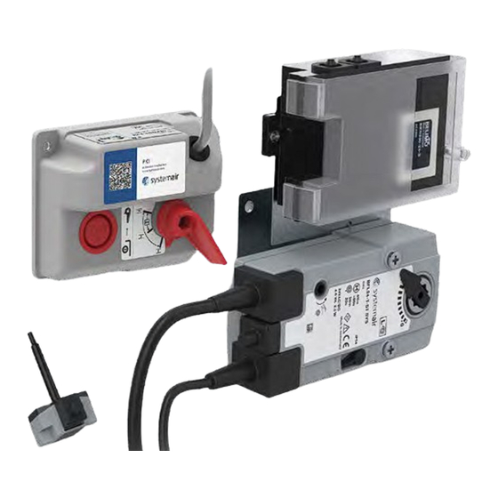
The activation mechanism for PKIR and PKIS fire dampers is a crucial part of the damper. Its purpose is to drive the fire damper blade between the open and closed positions. In case of emergency, AM-PKI will close the damper blade and remain closed to fulfill classification parameters of the fire damper. Activation mechanism types for PKIR and PKIS dampers are interchangeable with some degree of compatibility. -
Page 4: Warnings
Before installing an AM-PKI accessory, check the mechanism compatibility by comparing the 3-digit code provided on the AM-PKI label with codes listed on the fire damper body label. If your fire damper label has your mechanism compatibility code listed, the mechanism can be installed. -
Page 5: Damper Preparation
201805 | User Manual AM-PKI | 5/20 Damper Preparation Manually Operated Activation Mechanism The damper blade must be in the closed position for activation mechanism removal IMPORTANT: Danger of electric shock! Switch off the power supply before working on any electrical equipment. -
Page 6: Actuator Operated Activation Mechanism
6/20 | User Manual AM-PKI | 201805 Actuator Operated Activation Mechanism The damper blade must be in the closed position for activation mechanism removal IMPORTANT: Danger of electric shock! Switch off the power supply before working on any electrical equipment. -
Page 7: Removal Of The Activation Mechanism
201805 | User Manual AM-PKI | 7/20 Removal of the Activation Mechanism Manually Operated Activation Mechanism Fig 4: (part 1/2) Manually operated activation mechanism removal 1 To remove the activation mechanism, the damper blade must be in the closed position (B) Look for a small black plug (A) sitting flush with the damper body. - Page 8 8/20 | User Manual AM-PKI | 201805 Fig 4: (part 2/2) Manually operated activation mechanism removal 3 Pull the red lever out together with its seal. 4 Loosen and remove the two visible nuts holding the cover in place. 5 Make sure the mechanism is not connected to a power source.
-
Page 9: Actuator Operated Activation Mechanism
201805 | User Manual AM-PKI | 9/20 Actuator Operated Activation Mechanism Fig 5: Actuator operated activation mechanism removal 1 To remove the activation mechanism, the damper blade must be in the closed position. 2 Remove the screws from the thermal fuse (A) with a screwdriver. -
Page 10: Installing The Activation Mechanism
10/20 | User Manual AM-PKI | 201805 Installing the Activation Mechanism Manually Operated Activation Mechanism For installing the activation mechanism, the blade must be in the closed position. You should clearly see the coulisse slot hole It is recommended to inspect the free movement of the blade and the closure gasket for its condition... - Page 11 201805 | User Manual AM-PKI | 11/20 Fig 6: (part 2/2) Manually operated activation mechanism installation 5 Align the mechanism plastic cover and fix the two remaining nuts in the opposite corners with maximum torque of 2 Nm (B) 6 Insert the red lever through the foam gasket and press onto the lever shaft (B). The red lever fits only...
-
Page 12: Actuator Operated Activation Mechanism
12/20 | User Manual AM-PKI | 201805 Actuator Operated Activation Mechanism For installing the activation mechanism, the blade must be in the closed position. You should clearly see the coulisse slot hole It is recommended to inspect the free movement of the blade and the closure gasket for its condition Fig 7: (part 1/2) Actuator operated activation mechanism installation 1 Look for a small black plug sitting flush with the damper body (A) Make sure the gaskets around the damper’s... - Page 13 201805 | User Manual AM-PKI | 13/20 Fig 7: (part 2/2) Actuator operated activation mechanism installation...
-
Page 14: Set The Damper Into Operation
14/20 | User Manual AM-PKI | 201805 Set the Damper into Operation After the mechanism installation, it is necessary to adjust the damper into its operating position – open the fire damper. Manually Operated Activation Mechanism Fig 8: Manually operated activation mechanism set into operation 1 Turn the mechanism lever into the “OPEN”... -
Page 15: Actuator Operated Activation Mechanism
201805 | User Manual AM-PKI | 15/20 Actuator Operated Activation Mechanism Fig 9: Actuator operated activation mechanism set into operation 1 Connect the electric driving mechanism to the relevant electric power supply. 2 The actuator is activated and adjusts the damper into its operating position. Through the inspection opening, inspect the correct position of the damper and the smooth movement of the blade IMPORTANT: Log the mechanism change in the Operation Journal of the fire damper. -
Page 16: Electrical Connections
16/20 | User Manual AM-PKI | 201805 Electrical Connections Electric parameters of the microswitches, electromagnets and actuators based on the type of activation mechanism and its connection schemes can be found in the “UserManual_PKIR_PKIS” under the section “Electrical Connections” or on Systemair DESIGN... -
Page 17: Actuator Operated Activation Mechanism
201805 | User Manual AM-PKI | 17/20 Actuator Operated Activation Mechanism 1 The fire damper must open automatically after the actuator circuit closes – the arrow on the actuator axis must show the 90° position. 2 Press the control switch (1) on the thermal fuse (Fig 11) and hold it until the fire damper is fully closed –... - Page 18 18/20 | User Manual AM-PKI | 201805...
- Page 19 201805 | User Manual AM-PKI | 19/20...
- Page 20 www.systemair.com...
Need help?
Do you have a question about the AM-PKI and is the answer not in the manual?
Questions and answers