Advertisement
CENTRAL MONITOR CONTROL
SAFETY PRECAUTION
Read the safety precautions carefully before installing the unit.
Stated below are important safety issues that must be obeyed.
Conform there is no abnormal phenomena during test operation after complete, then
hand the manual to the user.
Meaning of marks:
Means improper handling may lead to personal death or
WARNING
severe injury.
Means improper handling may lead to personal injury or
CAUTION
property loss.
WARNING
Please entrust the distributor or professionals to install the unit.
Installation by other persons may lead to imperfect installation, electric shock or fire.
Strictly follow this manual.
Imporper installation may lead to electric shock or fire.
Reinstallation must be performed by professionals.
improper installation may lead to electric shock or fire.
Do not disassemble your air conditioner at will.
A random disassembly may cause abnormal operation or heating, which may result in fire.
CAUTION
Do not install the unit in a place vulnerable to leakage of flammable gases.
Once flammable gases are leaked and left around the wire controller, fire may occure.
The wiring should adapt to the wire controller current.
Otherwise, electric leakage or heating may occur and result in fire.
The specified cables shall be applied in the wiring. No external force may be applied
to the terminal.
Otherwise, wire cut and heating may occur and result in fire.
Power Transformer
AC220V/AC8.5V
Remarks:
1. In the wiring, the part from Rs485 to Rs232 is only needed when connecting with PC.
And one PC can connect max. 16 outdoor CCM and 16 indoor CCM.
2. One outdoor CCM can connect max. 32 outdoor units. One indoor CCM can connect
max.64 indoor units.
3. The address of outdoor CCM and the address of outdoor units are set by manual.
Please refer to their owner's manual for setting.And the address of any two outdoor CCM
can't be the same, or the system can't work normally.
4. Power Supply, see the below figure.
INSTALLATION MANUAL
MODEL: SYSCONTROL CWC 02
Before using your unit, please read this manual carefully and keep it for future reference.
INSTALLATION PROCEDURE
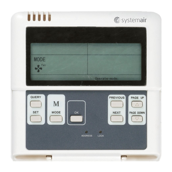
Wire Controller LCD
Outdoor CCM
Power Supply Connector
Thank you very much for purchasing our product.
Installation Location
Do not install the unit in a place with much oil, steam, sulfide gas. Otherwise, the
product may deform and fail.
Preparation before installation
1. Check whether the following assemblies are complete.
No.
1
Central Controller
2
Wood Mounting Screw
3
Mounting Screw
4
Installation Manual
5
Owner's Manual
Power Transformer
6
7
Network Match Resistance
2. Prepare the following assemblies on the site.
No.
3-core Shield Cable
1
RVVP-300/300 3×0.75mm
2
Switch box
Wiring Tube(Insulating
3
Sleeve and Tightening
Screw)
Note to installation of wire controller:
1. Never connect the network communication wire with strong power or put it into the same
Wiring Tube with the strong power. And at least 300-500mm distance should be left
between their wiring tubes.
2. The shield cable must be connected stable to the ground, or transmission may fail.
3. Do not attempt to extend the shield cable by cutting.
4. After finishing connection, do not use Megger to have the insulation check to the signal
wire.
Wire Controller
Back Cover
Wire Controller
Top Cover
Wire Controller
Board
Wire Controller
Bottom Cover
44
Wood Mounting
Screw (M4X20)
When installing the Wire Controller, you should
adjust the bottom of the Wire Controller Board to
the Wire Controller Back Cover which should be
49
fixed first, then press the other end of the Wire
60
Controller Board.
120
Never turn screws too tightly, or else the cover would be dented or the Liquid Crystal
breaks.
Please leave enough long cable for maintenance of the Wire Controller Board.
1
Version: MDV11I-002BW
OTHER PRECAUTIONS
Name
Qty.
1
3
M4X20(For Mounting on the Wall)
3
M4X25(For Mounting on the Electrical Switch Box)
1
1
1
AC 220V Input, AC 8.5V Output
1
Qty.
embeded
embeded
Name
into wall
onto wall
2
1
1
2 or 3
Turn a screwdriver at the concave on bottom panel
of the Wire Controller to remove the Back Cover
When installing the Wire Control-
ler Cover,be sure there is a hole in
the wall to avoid the Wire Control-
ler Back Cover being fixed directly
to the wall which is not allowed for
the Wire Joint extrudes out of the
Wire Controller Back Cover
CAUTION
202055100715
Remarks
MD-CCM02/E( or KCC-22)
120rhm
Remarks
One for communication with NIM,
One for communication with PC
Holes matche with the
86X86 Wiring box
Advertisement
Table of Contents

Related Manuals for SystemAir SYSCONTROL CWC 02


Summary of Contents for SystemAir SYSCONTROL CWC 02
- Page 1 CENTRAL MONITOR CONTROL INSTALLATION MANUAL MODEL: SYSCONTROL CWC 02 Version: MDV11I-002BW 202055100715 Thank you very much for purchasing our product. Before using your unit, please read this manual carefully and keep it for future reference. SAFETY PRECAUTION OTHER PRECAUTIONS Read the safety precautions carefully before installing the unit.
- Page 2 Wiring Sketch Map of CCM and Outdoor Units Both of following connection is correct(Total outdoor units number under one central controller ≤32) Outdoor unit Outdoor unit Outdoor unit Outdoor unit Outdoor unit Outdoor unit Central controller Outdoor unit Outdoor unit Outdoor unit Outdoor unit Outdoor unit...
Need help?
Do you have a question about the SYSCONTROL CWC 02 and is the answer not in the manual?
Questions and answers