Table of Contents
Advertisement
Quick Links
Advertisement
Table of Contents

Subscribe to Our Youtube Channel
Related Manuals for SystemAir HHFlex C


Summary of Contents for SystemAir HHFlex C
- Page 1 1177fil HHFlex C/R/P/S AHU Control Operating Instructions V8.00...
-
Page 2: Table Of Contents
Contents SAFETY CONSIDERATIONS General Avoid Electrocution Abbreviations used CONTROLLER DESCRIPTION Overview Power Supply Battery Indications Mapping of Inputs/Outputs Technical data 2.6.1 Common Data Controller 2.6.2 Communication 2.6.3 Casing 2.6.4 Inputs 2.6.5 Outputs 2.6.6 External display 2.6.7 TCP/IP port HUMAN MACHINE INTERFACE E-DSP External display unit Overview Log in... - Page 3 Fan speed control 4.3.1 Fixed Fan Speed Control 4.3.2 High / low speed operation 4.3.3 Air Flow Control 4.3.4 High / low air flow operation 4.3.5 Supply Duct Pressure Control 4.3.1 Supply and exhaust Duct Pressure Control 4.3.2 Indoor Air Quality Control Heat Recovery Monitoring 4.4.1 Low Supply Air Temperature Monitoring...
- Page 4 5.14 Recirculation air damper (CD06) 5.15 Mixing Box management 5.15.1 ON/OFF recirculation 5.15.2 Modulated recirculation as heating/cooling capacity 5.15.3 Minimum fresh air threshold 5.15.5 Modulated recirculation using CO2 sensor 5.15.6 Modulated recirculation as heating/cooling capacity with fresh air calculation 5.17 Fast building temperature warm-up/cool-down before an occupied period 5.18 Operation of chilled beams during unoccupied periods 5.19 Heat pump defrost 5.20 Minimum/maximum room temperature in an unoccupied period...
-
Page 5: Safety Considerations General
SAFETY CONSIDERATIONS General Installation, start-up and servicing of equipment can be hazardous if certain factors particular to the installation are not considered: operating pressures, presence of electrical components and voltages and the installation site (elevated plinths and built-up up structures). Only properly qualified installation engineers and highly qualified installers and technicians, fully trained for the product, are authorized to install and start-up the equipment safely. -
Page 6: Controller Description
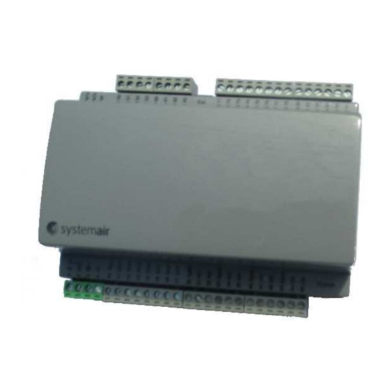
CONTROLLER DESCRIPTION HHFlex controller is an electronic control system to regulate Air Handling Units. The control system consists of two controllers which are described hereafter. Overview Controller Overview Port 2 and TCP/IP are only available on the main controller Power Supply Each controller operates at 24 VDC and has a power consumption of 4 VA (without load, without display). -
Page 7: Mapping Of Inputs/Outputs
Mapping of Inputs/Outputs... -
Page 8: Technical Data
Technical data 2.6.1 Common Data Controller Supply voltage 24 VAC ±15%, 50….60 Hz or 20…36 VDC Power consumption 4 VA (without load, without display) BTL approval EXOreal 3.1-1-02 or later +C output +24 V DC, 0,15 A, short-circuit proof Operating system EXOreal C Battery backup Memory and real-time clock, at least 5 years... -
Page 9: Human Machine Interface
HUMAN MACHINE INTERFACE E-DSP External display unit Overview The display menu system is accessed using seven buttons: The LEDs have the following functions: Designation Function Colour There are one or more Flashing red unacknowledged alarm(s) There are one or Fixed red more remaining, acknowledged alarm(s) You are in a dialogue... -
Page 10: Menu Tree External Display
Menu tree external display SOFTWARE DEFAULT SCREEN VERSION ACTUAL / ACTIVATE OUT OUT OF HOURS SETPOINTS OF HOUR OVERRIDE TIME OUTDOOR TEMPERATURE TEMPERATURE SUPPLY HUMIDITY INLET HUMIDITY TEMPERATURE ROOM DE-HUMIDITY INLET HUMIDITY SUPPLY HUMIDITY TEMPERATURE AIR VOLUME / EXTRACT SUPPLY FAN SUPPLY HUMIDITY ROOM HUMIDITY FANSPEED... -
Page 11: Access Levels External Display
Access levels external display VISIBLE FOR EVERYONE NO CHANGES CAN BE MADE VISIBLE FOR EVERYONE USERS LOGGED IN AS GUEST (3333) OR HIGHER CAN MAKE CHANGES VISIBLE FOR EVERYONE USERS LOGGED IN AS OPERATOR (2222) OR HIGHER CAN MAKE CHANGES ONLY VISIBLE FOR USERS LOGGED IN AS FACTORY Web panel Access to the data of HHFlex can be done thanks to a PC with Google Chrome. -
Page 12: Login Screen
Login Screen Klick on the login button There are three login levels: • Basic level with the lowest access; Login : Guest Password : 1111 • Level giving more access; Login : Operator Password : 2222 • Level with full access, for manufactory purpose only... -
Page 13: Overview Screen
Overview Screen Displays the process diagram and status of the unit. This is a read only folder. No settings can be made. 3.10 Dashboard screen Displays relevant modes and actual values. All values written in blue can be changed. As soon as a value has been changed and you have pressed enter, the value is downloaded to the HHFlex controller. -
Page 14: Actual/Setpoint Screen
3.11 Actual/Setpoint screen Displays relevant setpoints and actual values. All values written in blue can be changed. As soon as a value has been changed and you have pressed enter, the value is downloaded to the HHFlex controller. Users logged in as Guest can make changes on this pages. 3.12 Alarm Status screen Shows actual Alarms and Status of the unit. -
Page 15: Analog Inputs Screen
3.14 Analog Inputs screen Shows actual values for all analog inputs . For testing purpose only all functions can manually set here to a certain value. Only users logged in as Operator can make changes. BE CAREFUL: All settings which are made here will be executed. Protections like frost protection, max temperature electric heater and minimum airflow electric heater will be ignored. -
Page 16: Digital Inputs Screen
3.16 Digital Inputs screen Shows actual values for all digital inputs . For testing purpose only all functions can manually set here to a certain value. Only users logged in as Operator can make changes. BE CAREFUL: All settings which are made here will be executed. Protections like frost protection, max temperature electric heater and minimum airflow electric heater will be ignored. -
Page 17: Time Program Screen
3.18 Time Program screen Here you can set the time programs: • Run schedule. • Low Speed schedule. (Run schedule must be active) • Night cooling schedule. • Recirculation schedule. • Pump test schedule. • Holiday program All values written in blue can be changed by users logged in as Guest or Operator. As soon as a value has been changed and you have pressed enter, the value is downloaded to the HHFlex controller. -
Page 18: Settings Screen
3.19 Settings screen All values written in blue can be changed by users logged in as Operator. As soon as a value has been changed and you have pressed enter, the value is downloaded to the HHFlex controller. Only users logged in as Operator can make changes BE CAREFUL: Bad PID parameters can lead to unstable control. -
Page 19: Hhflex - Basic Control Functions
HHFlex – BASIC CONTROL FUNCTIONS Temperature Control Room Temperature Max. Cooling Hysteresis set by user HR + Gradual Cooling Free Cooling Threshold set function of by Advanced User Free Cooling extract air temp Heat Recovery (HR) Hysteresis set by user HR + Gradual Heating Max. -
Page 20: Room Air Temperature (Tt05) Control
4.2.1 Room air temperature (TT05) control To activate this function select room temp. in the configuration menu If OAT (TT06)correction is selected there is outdoor compensation on setpoint according the graph: RAT (TT05) setpoint correction +2 K -2 K 50°C OAT °C (TT06) -
Page 21: Extract Air Temperature (Tt03) Control
4.2.2 Extract air temperature (TT03) control To activate this function select Extract air temp. in the configuration menu If OAT (TT06) correction is selected there is outdoor compensation on setpoint according the graph: EAT (TT03) setpoint correction +2 K -2 K OAT °C (TT06) The temperature is fine controlled only in occupied mode. -
Page 22: Fan Speed Control
Fan speed control Different options for ventilation control can be selected: • Fixed fan speed control (low or high speed) • Air flow control (low or high airflow) • Supply duct pressure control • Supply and exhaust duct pressure control •... -
Page 23: Supply And Exhaust Duct Pressure Control
4.3.1 Supply and exhaust Duct Pressure Control To activate this function, set Fan control to Constant pressure in the configuration menu. Setpoint for this function is available in the menu Actual/Setpoint, Static duct pressure. The actual supply airflow rate is measured, while the pressure in the supply and exhaust duct is controlled at the required setpoint.. -
Page 24: Filter Monitoring Equipped With A Pressure Sensor
Filter Monitoring equipped with a pressure sensor Parameters for this function are available in the menu Settings. The supply (PT01) and extract (PT02) filter section is equipped with a pressure sensor connected to EXOline connected to the controller. If the pressure drop across the filter exceeds the preset value an internal timer is started. After an elapsed time of 60 minutes (by default) a service alert is generated. -
Page 25: Building Fire Management
Building Fire Management Parameters for this function are available in the Configuration menu Extra settings. The controller has a digital input for a fire alarm coming from the building system. When a ‘fire alarm’ is detected (generated by the BMS), the unit will start to run in Fire mode according the selected fire scenario. -
Page 26: Water Coil Frost Protection (Ta01)
Water Coil Frost Protection (TA01) A switching frost thermostat (TA01) is located downstream the hot water coil in order to prevent it from freezing in case of insufficient hot water supply. Capillary temperatures over a length of 300mm below the predefined alarm level generate a frost alarm and the unit will go into frost mode. -
Page 27: Change-Over Water Coil For Heating And Cooling
Change-over water Coil for Heating and Cooling Parameters for this function are available in the menu Actual/Setpoint and Settings. For systems with heat pump, a single coil for heating and cooling is used. This coil has to operate as a change-over coil to perform the heating function or cooling function in the AHU. -
Page 28: Warm Up At Unit Start Up
5.8.5 Warm Up at Unit Start Up This function is not active when indoor unit is selected To avoid unintentional frost alarm, a startup delay mode for winter operation is programmed. If the outdoor temperature (TT06) is below a preset value (default +5°C), the fans will only be started after a fixed preset time delay (5 min) in order to pre-heat the heating coil. -
Page 29: Electrical Reheating Coil
Electrical reheating Coil Parameters for this function are available in the menu Actual/setpoint and Settings. 5.9.1 Temperature Control If heat recovery is not enough to control temperature, the electrical booster heater is basically controlled as shown in the sketch below. Pulse Width 100% Measured Value... -
Page 30: Electrical Pre-Heating Coil
5.10 Electrical pre-heating Coil Parameters for this function are available in the menu Actual/Setpoint and Settings. 5.10.1 Heat Recovery Frost Protection The temperature entering the heat recovery exchanger is controlled as shown in the sketch below. Pulse Width 100% Measured Value Setpoint A PID controller is used. -
Page 31: Hot Water Pre-Heating Coil
5.11 Hot water pre-heating Coil Parameters for this function are available in Actual/setpoint and Settings. 5.11.1 Heat Recovery Frost Protection The temperature entering the heat recovery exchanger is controlled as shown in the sketch below. Valve Opening (VC03) 100% Pump (CP03) On &... -
Page 32: Direct-Expansion Coil
5.12 Direct-expansion coil Cooling/Heating can be ensured by an R410A direct-expansion coil (DX01), connected to a cooling only condensing unit or a reversible unit. The AHU with a direct-expansion coil is supplied with an additional air temperature (TT04) sensor located upstream of the coil. 5.12.1 Condensing unit/reversible unit with staged capacity The units with staged capacity cannot be directly controlled by the HHFlex controller. -
Page 33: Mixing Box Management
5.15 Mixing Box management A mixing box (3-damper arrangement) can be used to modulate the air recirculation from extract to supply duct. Exhaust (Digital) OUTDOOR INDOOR Recirculation (Analog) Outdoor (Analog) Commands Output command Output command Output command 100% 100% Close Open command command... -
Page 34: Modulated Recirculation Using Co2 Sensor
5.15.5 Modulated recirculation using CO2 sensor This control mode uses the logic of the heatcool modulation corrected by the requested fresh air value. Minimum fresh air threshold The minimum fresh air threshold value is now calculated using PI loop, based on co2PID parameters used for CO2 fancontrol, controlling the recirculation ratio with the CO2/IAQ sensor feedback. -
Page 35: Fast Building Temperature Warm-Up/Cool-Down Before An Occupied Period
5.17 Fast building temperature warm-up/cool-down before an occupied period This function can only be used if the HHFlex controller is configured to control the room temperature (TT05) or the extract air temperature (TT03). If the OAT (TT06) is below a certain threshold and the temperature controlled is offset by more than 2K compared to the setpoint, temperature warm-up/cool-down will be activated. -
Page 36: Humidification Control
5.21 Humidification control If the duct system comprises a humidifier suitable for modulating performance control, the AHU controller is programmed to control the minimum humidity of the air in the building. The humidity can be controlled on the basis of relative humidity of the supply air (MT02), -extract air (MT03), or relative humidity in a (representative) room (MT05). -
Page 37: Default Settings For Relative Humidity Control
5.21.2 Default settings for relative humidity control humidifier enabled if flow signal above minimum and control signal > 25% humidifier disabled if flow signal below minimum or control signal < 10% setpoint humidity supply air setpoint humidity extract air ... -
Page 38: Dehumidification Control
5.23 Dehumidification control The software in the controller is pre-programmed to control the maximum humidity in the air. The unit configuration however shall be suited for this application if this control scenario is selected. Dehumidification control requires a re-heater downstream the cooling coil. To protect the coil against freezing at low outdoor temperature and/or a failing heat recovery system, a water glycol fluid in the cooling system is mandatory (or DX cooling coil). -
Page 39: Diagnostics & Troubleshooting
DIAGNOSTICS & TROUBLESHOOTING General The HHFlex control system has many fault tracing aid functions. The web interface and its various menus give access to all unit operating conditions. If an operating fault is detected, an alarm is activated and an alarm message is displayed in the alarm list available in the Alarm Status menu. -
Page 40: Alarms List
Alarms List Alarm Description Reset Type Probable cause Action taken by the control Unit with heat recovery only Low Supply Air Unit is stopped for 50 minutes then Automatic During 10 minutes, SAT < SAT Temperature Alarm restarted. controlled point – 3 K Unit with heat recovery only High Supply Air Automatic... - Page 41 Alarm Description Reset Type Probable cause Action taken by the control - Derated mode: Warning & go to low fixed speed fan control - Unit stopped Supply Fan Pressure Defective sensor or installation Manual Unit stopped Failure fault Exhaust Fan Pressure Defective sensor or installation Manual Unit stopped...
-
Page 42: Bus Communication
BUS COMMUNICATION General The HHFlex controller is capable of communicating via RS485(Modbus) and TCP/IP(BACnet/IP) Modbus Modbus communication takes place via RS485 (port 2, main controller) or via IP (IP port, main controller). 7.2.1 Communication Settings The Modbus communication settings can be configured in the web panel in the Settings menu or with the external display unit under Settings =>... -
Page 43: Bacnet Ip
BACnet IP BACnet communication takes place via IP (IP port, main controller). -
Page 44: Annex 1 - Bacnet Protocol Implementation And Conformity
ANNEX 1 - BACNET PROTOCOL IMPLEMENTATION AND CONFORMITY... - Page 47 Systemair.B.V. Zanddonkweg 7a, 5144 NX Waalwijk The Netherlands Phone: +31 (0)85 00 66 200 www.systemair.nl...
Need help?
Do you have a question about the HHFlex C and is the answer not in the manual?
Questions and answers