Table of Contents
Advertisement
Quick Links
Advertisement
Table of Contents

Subscribe to Our Youtube Channel
Related Manuals for Vents VUTR 280 V EC


Summary of Contents for Vents VUTR 280 V EC
- Page 1 USER’S MANUAL VUTR 280 V EC VUTR 280 VE EC Heat recovery air handling unit...
-
Page 2: Table Of Contents
VUTR 280 V (E) EC CONTENTS Safety requirements ..................................2 Purpose ........................................ 4 Delivery set ......................................4 Designation key ....................................4 Technical data ....................................5 Design and operating principle ............................7 Installation and set-up................................8 Connection to power mains ..............................11 Technical maintenance ................................ - Page 3 • Do not change the power cable length at your own discretion. Do not bend the power • Do not lay the power cable of the unit in cable. Avoid damaging the power cable. Do close proximity to heating equipment. not put any foreign objects on the power cable.
-
Page 4: Purpose
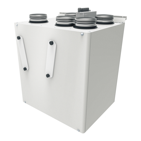
VUTR 280 V (E) EC PURPOSE The unit is designed to ensure continuous mechanical air exchange in houses, offices, hotels, cafes, conference halls, and other utility and public spaces as well as to recover the heat energy contained in the air extracted from the premises to warm up the filtered stream of intake air. -
Page 5: Technical Data
IP44 for the unit motors The unit design is constantly being improved, thus some models may be slightly different from those described in this manual. TECHNICAL DATA Parameter VUTR 280 V EC VUTR 280 VE EC Unit voltage [V/50 (60) Hz] 1~ 230... - Page 6 VUTR 280 V (E) EC OVERALL DIMENSIONS OF THE UNIT [mm] Ø D Model VUTR 280 V (E) EC 754 630 * The unit is equipped with height adjustable feet to compensate for uneven flooring. www.ventilation-system.com...
-
Page 7: Design And Operating Principle
DESIGN AND OPERATING PRINCIPLE The unit has the following operating principle: Warm stale extract air from the room flows to the unit, where it is filtered. Then the air is moved through the rotary heat exchanger and is exhausted outside with the extract fan. Clean cold air from outside is moved to the intake filter. -
Page 8: Installation And Set-Up
VUTR 280 V (E) EC INSTALLATION AND SET-UP READ THE USER'S MANUAL BEFORE INSTALLING THE UNIT. THE UNIT MUST BE MOUNTED BY A QUALIFIED EXPERT ONLY, PROPERLY TRAINED AND HAVING THE REQUIRED TOOLS AND MATERIALS. While installing the unit, provide enough access for maintenance or repair work. When selecting an installation location of the unit, provide free opening of the service panel. - Page 9 Attach the wall mounting bracket to the wall using dowels with screws (not included in the delivery set). Attach the wall mounting bracket to the wall considering the wall material and the unit weight. Install the unit on the mounting bracket. Suspend it carefully. Make sure the unit is fastened securely prior to operation. UNIT FLOOR MOUNTING Place the unit on a flat, stable surface that has sufficient load capacity matching the unit weight and meets safety requirements.
- Page 10 VUTR 280 V (E) EC HUMIDITY SENSOR MOUNTING The HV2 humidity sensor is not included in the delivery set and can be ordered separately. To install the humidity sensor, take off the front panel and remove the extract filter out of the unit. Install the humidity sensor into the mounting bracket on the inner side of the unit.
-
Page 11: Connection To Power Mains
CONNECTION TO POWER MAINS POWER OFF THE POWER SUPPLY PRIOR TO ANY OPERATIONS WITH THE UNIT. THE UNIT MUST BE CONNECTED TO POWER SUPPLY BY A QUALIFIED ELECTRICIAN. THE RATED ELECTRICAL PARAMETERS OF THE UNIT ARE GIVEN ON THE MANUFACTURER’S LABEL. ANY TAMPERING WITH THE INTERNAL CONNECTIONS IS PROHIBITED AND WILL VOID THE WARRANTY. - Page 12 VUTR 280 V (E) EC EXTERNAL CONTROL UNITS WIRING DIAGRAM OF THE VUTR 280 V(Е) EC A17/A18 UNITS GND~ ~24V 0-10V ~24V SM1* P1** th-Tune PK1* Kitchen hood SM2* – Electric shock hazard! Design Name Model Wire*** SM1* Exhaust or supply air damper electric actuator LF230 2x0.75 mm SM2*...
- Page 13 EXTERNAL CONTROL UNITS WIRING DIAGRAM OF THE VUTR 280 V(Е) EC A21 UNITS NO C 0-10V +24V +24V 6 7 8 9 10 11 12 13 14 15 16 17 18 19 20 21 22 +24V GND 0-10V +24V KH1.2* PK1* Boost* CO2*...
-
Page 14: Technical Maintenance
VUTR 280 V (E) EC TECHNICAL MAINTENANCE DISCONNECT THE UNIT FROM POWER SUPPLY BEFORE ANY MAINTENANCE OPERATIONS! Maintenance operations of the unit are required 3-4 times per year. They include general cleaning of the unit and the following operations: 1. Filter maintenance. Dirty filters increase air resistance in the system and reduce supply air volume. - Page 15 3. Fan maintenance (once per year). Even in case of regular maintenance of the filters, some dust may accumulate inside the fans and reduce the fan performance and supply air flow. Clean the fans with a soft cloth or a brush. Do not use water, aggressive solvents, or sharp objects as they may damage the impeller.
-
Page 16: Storage And Transportation Regulations
VUTR 280 V (E) EC STORAGE AND TRANSPORTATION REGULATIONS • Store the unit in the manufacturer’s original packaging box in a dry closed ventilated premise with temperature range from +5 ˚С to +40 ˚С and relative humidity up to 70 %. •... -
Page 17: Manufacturer's Warranty
MANUFACTURER’S WARRANTY The product is in compliance with EU norms and standards on low voltage guidelines and electromagnetic compatibility. We hereby declare that the product complies with the provisions of Electromagnetic Council Directive 2014/30/EU, Low Voltage Directive 2014/35/ EU and CE-marking Directive 93/68/EEC. This certificate is issued following test carried out on samples of the product referred to above. The manufacturer hereby warrants normal operation of the unit for 24 months after the retail sale date provided the user's observance of the transportation, storage, installation, and operation regulations. - Page 18 VUTR 280 V (E) EC www.ventilation-system.com...
-
Page 19: Certificate Of Acceptance
CERTIFICATE OF ACCEPTANCE Unit Type Heat recovery air handling unit Model VUTR 280 V __ EC A___ Serial Number Manufacture Date Quality Inspector’s Stamp SELLER INFORMATION Seller Address Phone Number E-mail Purchase Date This is to certify acceptance of the complete unit delivery with the user’s manual. The warranty terms are acknowledged and accepted. - Page 20 V140-2EN-02...
Need help?
Do you have a question about the VUTR 280 V EC and is the answer not in the manual?
Questions and answers