
Related Manuals for Vents VUT2 250 P EC


Summary of Contents for Vents VUT2 250 P EC
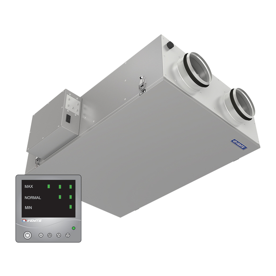
- Page 1 USER’S MANUAL Heat (Energy / Heat and Energy) Recovery Air-Handling Unit VUT2 250 P EC VUE2 250 P EC VUTE2 250 P EC...
-
Page 2: Table Of Contents
VU..2 250 P ЕС VU..2 250 P ЕС CONTENTS Safety requirements Introduction Delivery set Designation key Main technical data Unit design and operating logic Mounting and set-up Condensate drainage Connection to power mains Unit control Technical Maintenance Fault handling Storage and transportation rules Manufacturer's warranty Acceptance certifi cate Seller information... -
Page 3: Safety Requirements
SAFETY REQUIREMENTS • Read the user’s manual carefully prior to installing and operating the heat (energy / heat and energy) recovery air-handling unit (hereinafter «Unit»). • Fulfi l the operation manual requirements as well as the provisions of all the applicable local and national construction, electrical and technical codes and standards. - Page 4 VU..2 250 P ЕС VU..2 250 P ЕС SAFETY PRECAUTIONS TO BE FOLLOWED WHILE OPERATING THE UNIT. Do not wash the unit Do not touch the unit with water. controls with wet hands. Avoid penetration Do not carry out the unit water onto the electric maintenance with wet hands.
-
Page 5: Introduction
INTRODUCTION The present user’s manual consisting of the technical details, operating instructions and technical specifi cation applies to the installation and mounting the VU__2 250 P EC heat (energy / heat and energy) recovery air-handling unit (hereinafter «Unit»). Due to the ability to reduce heat/energy losses by means of recycling heat (energy / heat and energy) recovery air-handling units have become an important element of energy-effi cient spaces. -
Page 6: Designation Key
VUT - Heat Recovery Ventilation VUE - Energy Recovery Ventilation; VUTE - Energy and Heat Recovery Ventilation. MAIN TECHNICAL DATA * - Only for VUT2 250 P EC and VUTE2 250 P EC units. Fig. 1. Outside and connecting dimensions of the unit... - Page 7 Figure 1 and in Table 1. The unit design is regularly improved, so some models can slightly diff er from those ones described in this manual. Table 1 . Unit Technical Parameters VUT2 250 P EC Model VUE2 250 P EC VUTE2 250 P EC...
-
Page 8: Unit Design And Operating Logic
G4 extract fi lter. G4 supply fi lter. Condensate drain pan: - for VUT2 250 P EC unit - 2 pieces - for VUTE2 250 P EC unit - 1 piece - VUE2 250 P EC units have no drain pan. -
Page 9: Mounting And Set-Up
Mounting and set-up Make sure that the installation location provides for suffi cient space as required for the unit maintenance. The units are suspended to the ceiling by means of belts rigidly fastened to a horizontal surface (Fig. 3) or threaded rods screwed into dowels which are buried into the ceiling. Prior to the installation check the unit casing for any left-over foreign objects such as plastic fi lm or paper. -
Page 10: Connection To Power Mains
VU..2 250 P ЕС VU..2 250 P ЕС Fig. 4. Condensate drainage A condensate drainage system is used in premises with above-zero temperatures. To enable operation at subzero temperatures the condensate drainage system must be equipped with heat insulation and pre-heating facilities. Connection to power mains Disconnect the unit from the power supply prior to any operations on the unit! The unit must be plugged into a properly installed power socket with an earthed terminal. -
Page 11: Unit Control
UNIT CONTROL The unit control panel is designed to run two alternative software versions: • DUO/6M901580B (installed by default); • DUO/6Т901580. The software version installed on a specifi c unit is specifi ed on the label attached to the rear side of the control panel. - Page 12 VU..2 250 P ЕС VU..2 250 P ЕС Table 2. Control panel ventilation mode display Software version Mode Indicator combination DUO/6M901580B DUO/6Т901580 Minimum air fl ow Time: unlimited Minimum air fl ow +80 Minimum air fl ow +80 NORMAL Time: 30 minutes Maximum air fl ow Time: unlimited Setup mode.
- Page 13 Table 3. Indication Air fl ow [m...
- Page 14 VU..2 250 P ЕС VU..2 250 P ЕС 3. Control panel connection. The control panel view from the connector side is given on Fig. 6. 1 - U_EC1 control voltage; 2 - U_EC2 control voltage; 1 2 3 4 3 - +12V supply voltage; 4 - Negative power lead.
-
Page 15: Technical Maintenance
TECHNICAL MAINTENANCE Maintenance operations of the unit are required 3-4 times per year. Maintenance includes regular cleaning and the following operations: Filter maintenance. Filter Maintenance Frequency: • DUO/6Т901580 - 3-4 times a year; • DUO/6M901580B - according to the fi lter service alert generated every 3,000 operating hours (according to the integrated hour meter). - Page 16 VU..2 250 P ЕС VU..2 250 P ЕС Fig. 8. Filter and heat exchanger maintenance Fig. 9. Control unit maintenance...
-
Page 17: Fault Handling
FAULT HANDLING Possible malfunctions and their elimination Problem Possible reasons Fault handling Make sure that the unit is properly Fan(s) do(es) No power supply. connected to the power mains and make not start any corrections, if necessary. Exhaust fi lter clogging. Clean or replace the extract fi lter. -
Page 18: Storage And Transportation Rules
VU..2 250 P ЕС VU..2 250 P ЕС STORAGE AND TRANSPORTATION RULES The unit must be stored in the original packing in a dry ventilated area at temperatures from +10 °C to +40 °C and maximum relative humidity of 80% (at 20 ºC). The air in the storage space must not contain any vapours or admixtures which may lead to corrosion or compromise the insulation and seals. - Page 19 • Unit repair by any persons without the manufacturer’s authorization; • Expiration of the unit warranty period; • User’s violation of the unit transportation regulations; • User’s violation of the unit storage regulations; • Wrongful acts against the unit committed by a third party; •...
-
Page 20: Acceptance Certificate
VU..2 250 P ЕС VU..2 250 P ЕС ACCEPTANCE CERTIFICATE Product Type Heat (Energy/Heat and Energy) Recovery Air-Handling Unit Model VU______2 250 P EC Serial Number Manufacturing Date is compliant with the technical specifi cations and is hereby declared ready for service. We hereby declare that the product complies with the essential protection requirements of Electromagnetic Council Directive 2004/108/EC, 89/336/EEC and Low Voltage Directive 2006/95/EC, 73/23/EEC and CE-marking Directive 93/68/EEC on the approximation of the laws of the Member States relating to electromagnetic... -
Page 21: Warranty Card
WARRANTY CARD Product type Heat (energy/heat and energy) recovery air-handling unit Model VU______2 250 P EC Serial number Manufacturing date Sales date Seller’s seal Warranty period Sales company... - Page 22 V83EN-07...
Need help?
Do you have a question about the VUT2 250 P EC and is the answer not in the manual?
Questions and answers