Advertisement
Quick Links
Advertisement

Related Manuals for Comica CVM-WS60 COMBO


Summary of Contents for Comica CVM-WS60 COMBO
- Page 1 CVM-WS60 COMBO UHF 1-Trigger-2 Flexible Mini Wireless Microphone User Manual...
-
Page 2: Main Features
Foreword Thanks for purchasing COMICA WS60 COMBO UHF 1-Trigger-2 flexible mini wireless microphone. To ensure the correct use and safety of the product, please carefully read this instruction before using and properly assemble and operate. Main Features . 1-Trigger-2, Universal for Smartphone & Camera . -
Page 3: Main Parts
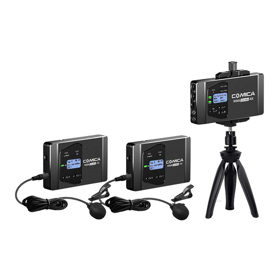
Packing List Main Parts: Lavalier Transmitter(TX) Hand-held Transmitter (HTX) Receiver(RX) Purchase Options: WS60 COMBO= 2TX + RX WS60 HTX:... - Page 4 Accessories: 3.5mm Mic Audio Input Cable 3.5mm TRRS -3.5mm TRRS Audio Output Cable Belt Clip Wind Muff Portable Case Ball Head Tabletop Tripod USB-C Charging Cable User Manual Warranty Card CVM-WS60 COMBO UHF 1-Trigger-2 Flexible Mini Wireless Microphone User Manual...
- Page 5 Components and Instruction Components Lavalier Transmitter (TX) 1/4 Connecting Hole Reset Hole Belt Clip Connection Hole LCD Screen Group Selection Switch On-off / Muting Button Matching / Muting Status Light Indicator USB-C Charging Interface MIC / LINE IN Input Jack Group Switching Button LCF (Low Cut Filter) Switch...
- Page 6 Hand-held Transmitter (HTX) Microphone LCD Display On-off / RF Adjustment Button Group Switching Button AA Battery Tray...
- Page 7 Receiver (RX) Smartphone Clamp Locking Screw 1/4 Connecting Hole Reset Hole 1/4 Connecting Hole Group A Channel Selection Switch Group B Channel Selection Switch On-off Button Group A Working Status Light Indicator Group B Working Status Light Indicator Group A Volume Adjustment Dial Group B Volume Adjustment Dial USB-C Charging Interface 3.5mm Audio Output Jack...
- Page 8 Function Button Instruction Long Press Power ON/OFF Lavalier Muting Mode On-off/Muting Button Transmitter (The Mute Mode only works (TX) after the screen lighted up) Short Press Channel Selection Switch Short Press Channel Selection Group Switching Button Left is Group A Push Right is Group B LCF Switch...
- Page 9 On-Off Button Long Power ON/OFF Receiver Press (RX) Press is to select Group A`s Channel Selection Switch Short Channel Press Press is to select Group B`s Channel Push left to , Open Group A only Group Switching Button Push to middle , Open both Push Group A and Group B...
-
Page 10: Screen Display
Screen Display Lavalier Transmitter Normal Recording Low Cut Filter Antenna Icon Muting Normal Recording Power Indication Group A/B 11 579.125MHz Channel Audio Dynamic Bar Frequency Hand-held Transmitter Normal Recording Power Indication Channel Group A/B... - Page 11 Receiver Group B Signal Strength Mono Sound: Smartphone Mode: Group A Signal Strength Stereo Sound: Camera Mode: Power Indication Group A Group B Channel A Channel B Group A Volume Group B Audio Receiving Dynamic Bar Group A Audio Receiving Dynamic Bar Group B Volume Stereo Mode M/S Mode...
- Page 12 Indicator Light Instruction Normal Recording Status ( The status works for transmitter only. Lavalier Green Light Keeps on The receiver can pick up the sound when channel matched successfully. ) Transmitter (TX) Red Light Keeps on Muting Mode Red Light Flickers Low- power Reminder Green Light Keeps on Normal working status after channel matched successfully...
- Page 13 The matching methods of Receiver and Transmitter 1. Switch the Receiver’s Group to “A”, “B” or “A/B”, then switch the transmitter’s Group to corresponding “A” or “B” (Lavilier Transmitter) (Hand-held Transmitter) (Receiver) One-Triggered-One:Switch the Receiver’s Group to “A”or “B” One-Triggered-Two:Switch the Receiver’s Group to “A/B” 2.
- Page 14 Installation and Usage Lavalier Transmitter (TX) 1. Plug the USB-C charging cable into the USB-C charging interface then connect an external power for charging; Insert the reset pin into the reset hole to reset it when the device is crash Reset Hole USB-C Plug POWER 5V...
- Page 15 2. Insert the 3.5mm Mic Audio Input Cable into the MIC/ LINE IN Input Jack 3. Long press the On-off Button to open the transmitter...
- Page 16 4. Target the Mic to the audio source and check whether the Lavalier Transmitter is working properly according to the audio display bar on the screen. 1 0 d B 0 6 5 7 4 . 1 2 5 M H z Audio Dynamic Bar 5.
- Page 17 Hand-held Transmitter 1. Install the battery into the hand-held Transmitter’s battery tray according to their positive and negative electrode 2. Long press the On-off Button to start the hand-held transmitter 3. It can be used after channel matched successfully with Receiver Please refer to the matching steps for channel matching...
- Page 18 Receiver 1. Plug the USB-C charging cable into the USB-C charging interface then connect an external power for charging; Insert the reset pin into the reset hole to reset it when the device is crash Reset Hole USB-C Plug POWER 5V...
- Page 19 2. Using Methods 2.1 Method one: Using with Tripod 2.1.1 Connect Receiver and Tripod...
- Page 20 2.1.2 Rotate the four clamps to the front side.
- Page 21 2.1.3 Fixing the locking screw to an appropriate height, then clamp your smartphone in a suitable position...
- Page 22 2.1.4 Rotate the locking screw until it fastened and fix your smartphone It can be adjusted to different angles according to your needs (Vertical Mode) (Horizantal Mode)
- Page 23 2.1.5 Connect the receiver and your smartphone with 3.5mm-3.5mm Audio Output Cable This product uses 3.5mm TRRS output interface, phone with other interface should be prepared with corresponding adapter cable to use...
- Page 24 2.1.6 Plug your earphone into “ 3.5mm monitoring jack” to realize real time monitoring...
- Page 25 2.2 Method two: Using with your Camera 2.2.1 Connect your Camera to the Receiver with the ball head...
- Page 26 2.2.2 Insert the Mic Audio Input Cable into the 3.5mm jack of the Receiver and your Camera respectively...
- Page 27 2.2.3 Plug your earphone into “ 3.5mm monitoring jack” to realize real time monitoring 3. It can be used after channel matched successfully with Transmitter Please refer to the matching steps for channel matching...
- Page 28 Specification Lavalier Transmitter (TX) Channel Duration 8 hours Antenna Built-in Antenna Stray Radiation ﹤-60dBc Sound Delay ﹤20ms Audio Distortion ﹤0.5% Signal/ Noise ﹥65dB Audio Input Socket 3.5mm TRS Battery Li-po Battery 1150mAh 3.7V Dimension 104×65.2×18mm Working Temperature 0℃~+50℃ Storage Temperature -20℃~+60℃...
- Page 29 Hand-held Transmitter (HTX) Channel Duration 4 Hours Signal/Noise ﹥65dB Antenna Built-in PCB Antenna Stray Radiation ﹤-60dBc Sound Delay ﹤20ms Audio Distortion ﹤0.5% Battery AA Batteries×2pcs Dimension Φ 53.5 (MAX)×248mm Working Temperature 0℃~+50℃ Storage Temperature -20℃~+60℃...
- Page 30 Receiver (RX) Channel Duration 8 Hours Antenna Built-in Antenna Sensitivity -90dBm Sound Delay ﹤20ms Audio Distortion ﹤0.5% Radiation Frequency 20Hz~18KHz Signal/Noise ﹥65dB Audio Output Socket 3.5mm TRRS Monitor Interface 3.5mm TRS/TRRS Battery Li-po Battery 1150mAh 3.7V Dimension 134.5×65.4×18mm Working Temperature 0℃~+50℃...
- Page 31 The COMICA logo is trademark which is registered and owned by Commlite Technology Co.,Ltd Email: support@comica-audio.com...
Need help?
Do you have a question about the CVM-WS60 COMBO and is the answer not in the manual?
Questions and answers