Table of Contents
Advertisement
Operating Table Operators Manual
MOT-5602BW
This operating table is designed to support a patient during surgical procedures. Using it for
other purposes may result in damage or injury.
The operator and the person in charge of the maintenance of this operating table must read
this operator's manual thoroughly and understand the contents before operating, inspecting,
adjusting and maintaining it.
Keep this manual for reference in a place where is readily accessible.
MES-CK18-450-10EN Ver.2 2019.5
Advertisement
Table of Contents

Related Manuals for Mizuho MOT-5602BW


Summary of Contents for Mizuho MOT-5602BW
- Page 1 Operating Table Operators Manual MOT-5602BW This operating table is designed to support a patient during surgical procedures. Using it for other purposes may result in damage or injury. The operator and the person in charge of the maintenance of this operating table must read this operator's manual thoroughly and understand the contents before operating, inspecting, adjusting and maintaining it.
-
Page 2: Table Of Contents
Table of contents Introduction ………………………………………………………… 1 This manual ……………………………………………………………………… 1 Intended use and this product ………………………………………………… 1 Accessories ……………………………………………………………………… 2 Safety precaution ………………………………………………… 3 Read thoroughly before using ………………………………………………… 3 Labeling ………………………………………………………………………… 8 Component identification …………………………………………12 Main unit …………………………………………………………………………12 Control unit ………………………………………………………………………13 Operation ……………………………………………………………14 Installation and battery charging ………………………………………………14 Turning on/off the power ………………………………………………………18... -
Page 3: Introduction
. Introduction 1.1 This manual This manual contains information for safely and effectively using this product. Before operating this product, read this manual thoroughly to understand how to operate, inspect, adjust and maintain the product. Failure to follow these instructions could lead to serious injury. The safety information is categorized as per the following so that the contents of warnings and cautions, and the details of warnings and cautions which are labeled on the product may be comprehended. -
Page 4: Accessories
1.3 Accessories „ „ Standard components and accessories Mattresses (for head, back and hips, and legs) Control unit Main unit Operators manual... -
Page 5: Safety Precaution
. Safety precaution 2.1 Read thoroughly before using Never perform the following when you use the product. Otherwise, damage to the operating table, electrical shock, and/or fire may occur. (1) Head plate and leg plate Do not step or sit on the head plate or the leg plate(s). The operating table may tip over resulting in injury. WARNING Before lowering the table or placing it in a reverse Trendelenburg position, check if there are any devices... - Page 6 (2) Control unit • Do not forcibly pull on the control unit cord. • Do not subject the control unit to strong shocks. The control unit may get CAUTION damaged. (3) Upper area of the cover Do not put any object on the cover. When the table moves downward, or into the CAUTION Trendelenburg or the lateral tilt position, the slide...
- Page 7 • Make sure to inspect and maintain the operating table before and after use. The operating table may require replacement of the parts due to significant wear, deterioration, and/or breakage depending on the usage conditions and frequency of usage. • For preventive maintenance and inspections, contact your distributor or Mizuho directly. ● Antistatic measure •...
- Page 8 4. As with step 3, disinfect the surfaces of the tables and side rails. 5. Wipe off the operating table with a clean dry cloth 15 minutes after disinfecting it. • Make sure to use Mizuho authorized disinfectants. The disinfectants are as shown below.
- Page 9 ● Moving and transporting • Follow the procedures below to move the operating table. CAUTION * Before moving the operating table, disinfect the entire operating table in order to prevent infection. 1. Turn off the power and disconnect the power cord from the medical grade outlet. 2. Check if the handles and levers are in fixed positions, and each section is fixed firmly.
-
Page 10: Labeling
2.2 Labeling The operating table is labeled at the locations shown as below. Before use, make sure to understand the contents of the labels. „ „ Warning and Caution labels (1) C655650 (2) C655608 (3) C653624 ... - Page 11 „ „ Other labels (1/2) (10) (11) (11) (19) (12) (10) (13) (18) (12) (14) (15) (16) (17) (10) C600516 (11) C655646 (12) C600020 (13) C655648 (14) C653515 (15) C653516 (16) C600559 (17) C653513 (18) C630006 ...
- Page 12 „ „ Other labels (2/2) (20) (20) (20) (20) (20) (23) (22) (21) (24) (27) (26) (25) (20) C653620 (21) C655691 (ASIA) (22) C655692 (ASIA) (23) C646067 (ASIA) C655689 (EU) C655690 (EU) C646070 (EU) ...
- Page 13 „ „ Labeling list Symbol Description Label no. Possibility of injury or even death if operates the table without (1) (2) (3) (4) (5) (6) following the warning. (7) (8) Refer to the operators manual (6) (9) (13) (18) General prohibition sign General mandatory action sign Emergency stop Equalization terminal...
-
Page 14: Component Identification
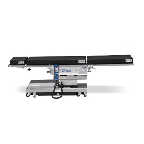
. Component identification 3.1 Main unit Emergency stop switch Control unit Leg plate (*1) Waist plate Mattress Back plate Head plate (*1) Leg plate flexing lever Leg plate fixing knob Side frame Side rail Sliding cylinder Head plate fixing knob Column Head plate flexing lever Base Fig. -
Page 15: Control Unit
3.2 Control unit MOT-5602BW Power lamp Pilot lamp Battery lamp PILOT POWER BATT. REV. TREND. TREND. Reverse Trendelenburg: Trendelenburg: Head down Head up TILT LEFT TILT RIGHT Lateral tilt: Left down Lateral tilt: Right down BACK UP BACK DOWN Back plate bending: Down... -
Page 16: Operation
. Operation 4.1 Installation and battery charging „ „ Installation space This product requires the installation space shown as below. 2.5 m or more 2.5 m or more 2.5 m or more 2.5 m or more „ „ Installing the operating table When this product is used with the power cord CAUTION... - Page 17 „ „ Attaching the control unit Align the connector with the guide and insert it into the receptacle properly. Insert the connector „ „ Detaching the control unit When you replace the control unit, detach the connector from the receptacle. Turn the connector ring in the direction of the arrow until it stops.
- Page 18 Medical grade outlet • The operating table battery life-span is about 2 years. Once it reaches its life-span, request your distributor or Mizuho for a battery replacement. • The life-span for the battery varies greatly depending Battery charging starts. on operating conditions.
- Page 19 „ „ Using the self-diagnostic function This product is equipped with an embedded self-diagnostic function capable of checking if the main unit and the control unit function are functioning properly. Connect the power connector of the product and the medical grade outlet with the power cord. ON/OFF Press of the control unit.
-
Page 20: Turning On/Off The Power
The power lamp (green) on the control unit lights up and the power is If a switch is continuously turned on. pressed for 3 minutes or more, its operation is halted. MOT-5602BW The halt condition continues PILOT POWER BATT. REV. TREND. - Page 21 The power lamp (green) on the control unit goes out. ON/OFF pressing on the control unit, the power of the battery MOT-5602BW is turned on. PILOT POWER BATT. REV. TREND. TREND. TILT LEFT...
- Page 22 The power lamp (green) and battery lamp (orange) on the control unit power, the power is and battery indicator lights up, and the power is turned on. automatically turned off if no MOT-5602BW operation is performed for 2 hours or more. PILOT POWER BATT.
- Page 23 The power lamp (green) and battery lamp (orange) on the control unit and battery indicator go out and the power is turned off. MOT-5602BW PILOT POWER BATT. REV. TREND.
-
Page 24: Operating The Emergency Stop Switch
4.3 Operating the emergency stop switch The emergency stop switch must be used only in an emergency. WARNING In an emergency, you can stop operating table from moving by pressing the emergency stop switch. „ „ Operating in an emergency Press the emergency stop switch. -
Page 25: Fixing And Unfixing The Operating Table
ENERGIZE TABLE UP Hold down and press NOTE The brake is activated to fix the operating table. • It takes about 7 to 8 seconds until the operating MOT-5602BW table is fixed or released. PILOT POWER BATT. TREND. REV. TREND. • If the brake cannot be TILT LEFT TILT RIGHT activated and the operating... -
Page 26: Tilting The Tabletop Laterally
4.5 Tilting the tabletop laterally When you tilt the tabletop laterally, make sure to use the fixture for the accessory of the Mizuho operating table. The patient may fall from the operating table. WARNING „ „ Tilting to the left NOTE • The maximum angle ENERGIZE Hold down and press TILT LEFT achieved in the right down The tabletop tilts to the left in the view from the head side. -
Page 27: Trendelenburg
4.6 Trendelenburg When you operate the Trendelenburg operation, make sure to use the fixture for the accessory of the Mizuho operating table. The patient may fall from the operating table. WARNING • When performing the head down operation, be careful that the head plate tip does not contact the floor. It may get damaged. CAUTION • When performing the head down operation, be careful that the head plate fixing handle does not contact the cover. It may get damaged. -
Page 28: Tilting The Back Plate
BACK UP achieved in the back plate The back plate moves up. up position is 90° to the level position. 90° MOT-5602BW • The maximum angle PILOT POWER BATT. REV. TREND. TREND. achieved in the back plate TILT LEFT TILT RIGHT down position is 40°... -
Page 29: Changing The Tabletop Height
ENERGIZE TABLE UP Hold down and press the floor to the tabletop The tabletop moves up. upper surface is 1000 mm (39.4 in). Move up MOT-5602BW • The minimum height from PILOT POWER BATT. the floor to the tabletop REV. TREND. TREND. TILT LEFT TILT RIGHT upper surface is 520 mm... -
Page 30: Sliding The Tabletop
The tabletop slides in the foot direction. and the buzzer will sound. 310 mm (12.2 in) When moving up the back MOT-5602BW Foot direction plate higher than the level PILOT POWER BATT. TREND. REV. TREND. -
Page 31: Flexing Or Reflexing The Tabletop
FLEX flexing (center up) does not The back plate flexes downward and the waist plate turns to the work and the buzzer will Trendelenburg head up position. sound. If the tabletop center is slid to the head direction MOT-5602BW Center up beyond the standard center PILOT POWER BATT. REV. TREND. TREND. position, the back plate... - Page 32 The leg plates may come in contact with the base and CAUTION get damaged. ENERGIZE Hold down and press REFLEX The back plate reflexes upward and the waist plate turns to the reverse Trendelenburg head down position. MOT-5602BW Center down PILOT POWER BATT. REV. TREND. TREND. TILT LEFT TILT RIGHT BACK UP...
-
Page 33: Returning To Level
NOTE Raising, sliding, and braking ENERGIZE Hold down and press LEVEL do not function. The tabletop returns to the level position after Trendelenburg, lateral tilting, back plate tilting, and flexing are worked. MOT-5602BW PILOT POWER BATT. REV. TREND. TREND. TILT LEFT TILT RIGHT BACK UP BACK DOWN... -
Page 34: Adjusting The Head Plate
4.12 Adjusting the head plate The head plate can be flexed in 15° increments, to 4 different positions upward (maximum 60°) and to 6 different positions downward (maximum 90°). The head plate can also be detached. „ „ Flexing the head plate • Make sure to tighten the head plate fixing knob securely. WARNING If the head plate moves, the patient may get injured. • The head plate weighs 7 kg (15 lbs). Pay special attention when handling it. - Page 35 „ „ Detaching the head plate The head plate weighs 7 kg (15 lbs). Pay special attention when handling it. WARNING It may drop and cause damage or injury. Loosen the two head plate fixing knobs located on the lower side of the back plate. Hold the both sides of the head plate firmly and pull it straight. Head plate fixing knob Head plate...
- Page 36 „ „ Attaching the head plate • Make sure to tighten the head plate fixing knobs securely. WARNING If the head plate moves, the patient may get injured. • The head plate weighs 7 kg (15 lbs). Pay special attention when handling it. It may drop and cause damage or injury. Hold the both sides of the head plate firmly and align the insertion shaft of the head plate with the reception hole in the back plate, and insert.
-
Page 37: Adjusting The Leg Plate
4.13 Adjusting the leg plate The leg plates are flexable, outward stretchable, and detachable. „ „ Flexing the leg plate The right and left leg plates can be independently flexed in 15° increments, to 6 different positions downward (maximum 90°). • Do not place it in a reverse Trendelenburg CAUTION position while the leg plates are down. The tips of the leg plates may come in contact with the base and get damaged. - Page 38 „ „ Outstretching the leg plates The leg plates are stretchable outward up to 90°. 90° 90° Turn leg plate fixing knob one revolution and a half, and loosen the leg plate fixing knob. Pull the leg plates outward. At the setting position, tighten the leg plate fixing knob to fix. Leg plate fixing knob Tight Loose Leg plate Make sure to lock the leg plate fixing knob. If the leg plates move, the patient may get injured. WARNING...
- Page 39 „ „ Detaching the leg plates A leg plate weighs 8 kg (18 lbs) (each). Pay special attention when handling it. It may drop WARNING and cause damage or injury. Hold the ends of the leg plate at the leg side. Turn the leg plate fixing knob.
- Page 40 „ „ Attaching the leg plates Hold the both ends of the leg plate and insert the leg plate shaft into the leg plate clutch. While holding the ends of the leg plate at the leg side, turn the leg plate fixing knob until the leg plate clutch engages with the leg plate shaft. Leg plate Leg plate clutch Leg plate fixing knob...
-
Page 41: Maintenance And Inspection
Make sure to inspect the items below before and after use. If there are any abnormalities, request your distributor or Mizuho for repairs. Otherwise it may cause WARNING problems during surgery. Inspect the items below. If there is any problem, request your distributor or Mizuho for repair. (1) Mattresses „ Before use • Check all the mattresses for any damage. - Page 42 (3) Table plates „ Before use • Check all the table plates for any damage. „ After use • Check all the table plates for any damage or dirt. (4) Control unit „ Before use • Press the switches on the control unit to see if all functions are working properly. (5) Oil leakage „...
-
Page 43: Periodic Replacement Parts
5.2 Periodic replacement parts Mizuho specifies that the following parts need to be periodically replaced for safety use. The replacement time is a rough standard. Earlier replacement may be required depending on the usage condition and/or usage frequency. Request your distributor or Mizuho for replacements. Control unit Battery Caster Brake rubber Power cord... -
Page 44: Specification
. Specification 6.1 Specification table Product name Operating Table MOT-5602BW Highest 1000 mm (39.4 in) Elevation range Lowest 520 mm (20.5 in) Trendelenburg Head down 25° angle Head up 25° Right down 20° Lateral tilt angle Left up 20° Back plate flexing 90°... -
Page 45: External View
Note 5: Rough dimension Note 6: Company standard (in case that appropriate maintenance and inspection is done) Note 7: Based on Mizuho's own validation data Note 8: IEC 60601-1 2012, Medical electrical equipment - Part1: General requirements for safety 6.2 External view... -
Page 46: Troubleshooting
. Troubleshooting „ „ When the control unit cannot be used The extra switch should be used only in an emergency. • Unlike the control unit, the extra switch has no function to halt the operation of the buttons. CAUTION • Always watch movement of the operating table when you operate the extra switch. - Page 47 „ Use the emergency brake release dial to release the brake Do not tilt the tabletop while the emergency brake release dial is in the "UNLOCK" position. WARNING The patient may fall from the operating table. In case of electrical trouble, the operating table can be moved by using the emergency brake release dial.
-
Page 48: Before Contacting For Repairs
à center up. position. ( Page 28) If the situation does not improve even if the above countermeasures are implemented, request repairs from your distributor or Mizuho. - Page 49 „ Warranty MIZUHO Corporation will repair defective parts of this product without charge for one year from the date of delivery/installment except for cases of damage caused by a third party’s repair, act of nature, improper use or damage on purpose. All other warranty terms and conditions are subject to regulations of MIZUHO...
-
Page 50: App.-1 Electromagnetic Compatibility
Operating Table MOT-5602BW should be observed to verify normal operation in the configuration in which it will be used. GUIDANCE AND MANUFACTURER’S DECLARATION – ELECTROMAGNETIC COMPATIBILITY Operating Table MOT-5602BW is intended for use in the electromagnetic environment specified below. The customer or the user of Operating Table MOT-5602BW should assure that it is used in such an environment. Emissions test Compliance Electromagnetic environment –... - Page 51 Operating Table MOT-5602BW is intended for use in an electromagnetic environment in which radiated RF disturbances are controlled. The customer or the user of Operating Table MOT-5602BW can help prevent electromagnetic interference by maintaining a minimum distance between portable and mobile RF communications equipment (transmitters) and Operating Table MOT-5602BW as recommended below, according to the maximum output power of the communications equipment.
- Page 52 GUIDANCE AND MANUFACTURER’S DECLARATION – ELECTROMAGNETIC IMMUNITY Operating Table MOT-5602BW is intended for use in the electromagnetic environment specified below. The customer or the user of Operating Table MOT-5602BW should assure that it is used in such an environment. Electromagnetic Immunity test IEC 60601 test level Compliance level environment – guidance Floors should be wood, Electrostatic concrete or ceramic tile.
- Page 53 GUIDANCE AND MANUFACTURER’S DECLARATION – ELECTROMAGNETIC IMMUNITY Operating Table MOT-5602BW is intended for use in the electromagnetic environment specified below. The customer or the user of Operating Table MOT-5602BW should assure that it is used in such an environment. IEC 60601 test Electromagnetic environment – Immunity test Compliance level level guidance Portable and mobile RF...
-
Page 54: App.-2 Glossary
App.-2 Glossary Base The light-blue portion of the figure below. Flex The back plate is bent upward or downward, the waist plate moves to the head-up or the head-down position, and the entire tabletop moves to the "Center up" or "Center down." Lateral tilt Tabletop of the operating table moves to the left-down or the right-down position in the view from the head side. - Page 55 Revision Record 10.04.2017 REV1 New release 05.2019 Version 2 Revision...
- Page 56 Autorized Representative Europe: Sale Agent Manufacturer: Emergo Europe B.V. Prinsessegracht 20, 2514 AP The Hague, The Netherlands 3-30-13 Hongo, Bunkyo-ku Tokyo 113-0033, Japan http://www.mizuho.co.jp...
Need help?
Do you have a question about the MOT-5602BW and is the answer not in the manual?
Questions and answers