Table of Contents
Advertisement
Quick Links
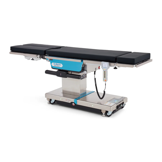
Operating Table MOT-VS700
Operator's Manual
This operating table is designed for medical operations. Using this operating table for any
other purpose other than this intended use may cause serious injury.
The operator and the person in charge of the maintenance of this operating table must read
this operator's manual thoroughly and understand the contents before operating, inspecting,
adjusting and maintaining it.
Keep this manual for reference in a place where is readily accessible.
MES-CK18-700-20EN Ver.4 2022-03-16
Advertisement
Table of Contents

Related Manuals for Mizuho MOT-VS700


Summary of Contents for Mizuho MOT-VS700
- Page 1 Operating Table MOT-VS700 Operator’s Manual This operating table is designed for medical operations. Using this operating table for any other purpose other than this intended use may cause serious injury. The operator and the person in charge of the maintenance of this operating table must read this operator's manual thoroughly and understand the contents before operating, inspecting, adjusting and maintaining it.
-
Page 2: Table Of Contents
Table of contents Introduction ………………………………………………………… 1 This manual ……………………………………………………………………… 1 Intended use and this product ………………………………………………… 1 Operation of this product ……………………………………………………… 2 Accessories ……………………………………………………………………… 2 Safety precaution ………………………………………………… 4 Read thoroughly before using ………………………………………………… 4 Labeling ………………………………………………………………………… 9 Section Introduction ………………………………………………13 Main unit …………………………………………………………………………13 Control unit ………………………………………………………………………14 Touch screen ……………………………………………………………………16... - Page 3 Maintenance and inspection ……………………………………65 Inspection before and after use ………………………………………………65 Periodic replacement parts ……………………………………………………67 Version information of the software ……………………………………………67 LAN connetor ……………………………………………………………………68 Specification ………………………………………………………69 6.1 Specification table ………………………………………………………………69 External view ……………………………………………………………………71 Troubleshooting ……………………………………………………72 Before contacting for repairs ……………………………………75 App.-1 Electromagnetic Compatibility ………………………………77 App.-2 Glossary ……………………………………………………………80...
-
Page 5: Introduction
. Introduction 1.1 This manual This manual contains information for safely and effectively using this product. Before operating this product, read this manual thoroughly to understand how to operate and inspect the product. Failure to follow these instructions could lead to serious injury. The safety information is categorized as per the following so that the contents of warnings and cautions, and the details of warnings and cautions which are labeled on the product may be comprehended. -
Page 6: Operation Of This Product
1.3 Operation of this product The description of the operations written in this manual focuses mainly on those to be done by the control unit. For some operations operable only by the touch screen, however, those by the touch screen are described. 1.4 Accessories „... - Page 7 „ Optional Control unit charging adapter Foot switch Single Leg Section・Mattress Double Leg Section・Mattress Mizuho Original Pad for Head Section for Back Section for Seat Section for Single Leg Section Type A Type A Type A Type A for Seat Section...
-
Page 8: Safety Precaution
. Safety precaution 2.1 Read thoroughly before using Never perform the following when you use the product. Otherwise, damage to the operating table, electrical shock, and/or fire may occur. Any serious incident that has occurred in relation to the device should be reported to the manufacturer and the competent authority in which the user and/or patient is established. (1) Head plate and leg plate Do not step or sit on the head plate or the leg plate(s). - Page 9 (2) Control unit • Do not forcibly pull the control unit cord. • Do not subject the control unit to strong shocks. The control unit may get damaged. CAUTION • While the reverse mode or the memory mode is set, press as necessary to put it back to the normal mode.
- Page 10 (6) Installation of the operating table • Do not install the operating table on an uneven floor. WARNING • Do not place a pad under the base for raising the operating Uneven floor table. The operating table may tip over resulting in injury. (7) Battery •...
- Page 11 • Make sure to inspect and maintain the operating table before and after use. The operating table may require replacement of the parts due to significant wear, deterioration, and/or breakage depending on the length of service and frequency of use. • For preventive maintenance and inspections, contact your distributor or Mizuho directly. ● Antistatic measure •...
- Page 12 4. As with step 3, disinfect the surfaces of the tables and side rails. 5. Wipe off the operating table with a clean dry cloth within 15 minutes after disinfecting it. • Make sure to use Mizuho authorized disinfectants. The disinfectants are as shown below. a) Sodium hypochlorite 0.1% (halogen containing compound) b) Hypo Alcohol (iodine color removing agent) c) Chlorhexidine (chlorhexidine gluconate 0.5%)
-
Page 13: Labeling
2.2 Labeling The operating table is labeled at the locations shown as below. Before use, make sure to understand the contents of the labels. „ Warning and Caution labels (10) (11) (1)* (2)* Single Leg Section *: Applied on both sides. Fig. - Page 14 „ Other labels (1/2) (12) (24) (23) (12) (13)* (22) (14) (18) (19) (20) (21) (25) *: Applied on both sides. Fig. shows MOT-VS700UKI with Double Leg Section (optional) (12) (16) (15) (17) (12) (14) C657310□ (13) C640018 (MOT-VS700UI) C640021 (MOT-VS700UKI) (12) C655001□...
- Page 15 „ Other labels (2/2) (27) (26) (26) (26) (26) (26) (31) (32) MOT-VS700UI (Fig. With Double Leg Section) (28) (29) (27) (26) (26) (26) (26) (26) (33) (26) MOT-VS700UKI (Fig. With Single Leg Section) (27) (28) (30) (37) (34) Double Leg Section (36) Single Leg Section (35)
- Page 16 „ Symbol mark for labeling Symbol Description Label no. Indicates a possibility of injury or even death if operates the (1) (2) (4) (5) (6) (7) table without following the warning. (8) (9) (10) (11) General prohibition sign (4) (5) General mandatory action sign.
-
Page 17: Section Introduction
. Section Introduction 3.1 Main unit Mattresses Leg plate(*1・ 2) Back plate attaching/ Seat plate detaching lever Lift-up unit(*3) Back plate(*2) Head plate(*2) Leg plate outstretching handle Leg plate attaching/ Head plate detaching lever flexing lever Head plate Side rail fixing handle Control unit Emergency... -
Page 18: Control Unit
3.2 Control unit Battery level Bluetooth connection Brake status Status number Menu Display for touch screen Warning for tipping over failure Battery power status Lift-up unit up Current position Control unit charge PILOT lamp request lamp Menu switch: Enter switch: Set position Display table position Memory switch: Level/Center lamp... - Page 19 „ Menu switch is pressed on the control unit, the screen display will change as the following. When you performing the lift-up or the beach chair operation, select the applicable screen with the menu switch. Usual screen Lift-up operation screen Current position Reverse orientation screen Beach chair operation screen...
-
Page 20: Touch Screen
3.3 Touch screen „ TOP PAGE screen BACK-UP CONTROLS screen MEMORY FUNCTION screen Power source Position in operation WIRELESS SETTING screen Memory mode being used Completion of memory position STOP AT LEVEL SETTING screen Language selection Battery indicator CAUTION/WARNING screen „... - Page 21 „ MEMORY FUNCTION screen TOP PAGE screen Settings of the position „ STOP AT LEVEL SETTING screen TOP PAGE screen Leg plate bending Trendelenburg Lateral tilt Table up/down Back plate bending Sliding Pause ON/OFF „ WIRELESS SETTING screen TOP PAGE screen IR code Bluetooth address Connect switch...
- Page 22 „ CAUTION/WARNING screen TOP PAGE screen „ Error screen Go to the previous screen Go to the previous screen NOTE • To prevent damages, the operating table may stop automatically during operation and display the caution/ warning or the error screen as shown above. For specific recovery procedures after the operating table stopped, refer to Page 73. •...
-
Page 23: Foot Switch (Optional)
3.4 Foot switch (optional) Reverse Trendelenburg: Lateral tilt: Table up Head up Right down Table down Trendelenburg: Lateral tilt: Head down Left down... -
Page 24: Operation
. Operation 4.1 Installation of the operating table „ Installation space This product requires the installation space shown as below. 2.5 m (98.43 in) or more 2.5 m (98.43 in) 2.5 m (98.43 in) or more or more 2.5 m (98.43 in) or more •... -
Page 25: Attaching/Detaching The Control Unit
4.2 Attaching/Detaching the control unit „ Attaching the control unit Align the connector with the guide and insert it into the receptacle properly. Insert the connector „ Detaching the control unit Turn the connector ring in the direction of the arrow until it stops. - Page 26 „ Using the control unit wirelessly NOTE • While being used wirelessly, The control unit can be detached from the main unit and used wirelessly. the control unit works on “Infrared mode” and “Bluetooth mode” are available for wireless the internal battery. The communication.
- Page 27 Charging NOTE The control unit cannot be used wirelessly when the battery level The battery of the control unit is low. If the control unit charge request lamp at the upper right of can be recharged only when the control unit blinks, connect the control unit with the wire and the battery is decreased immediately charge the control unit.
- Page 28 Using with the infrared mode • The operating table does not function if the IR code displayed on the touch screen does not match with CAUTION that on the monitor screen of the control unit. • When there are plural operating tables in one room, using the same IR code for them possibly causes cross talk resulting in malfunction.
- Page 29 Press to match the IR code displayed on the touch NOTE screen with that on the monitor screen of the control unit. • The default IR code is "7". • The IR code can be selected from 0 to 7. Press The IR code of the control unit is changed.
- Page 30 Using with the Bluetooth mode ● Bluetooth wireless operation • This function operates through the communication CAUTION via Bluetooth. Do not use this function if your facility’s rule bans wireless communication. • Do not use the wireless communications if there are concerns that the medical devices will be affected by the effects of the radio waves when they are simultaneously being used.
- Page 31 Hold down for 10 seconds. The IR code appears on the monitor screen of the control unit. Press The Bluetooth setting screen appears. Press to turn "BT Mode" to "ON". Press Press Press the function switch. NOTE A message "NOW CONNECTING" appears. After completion of If no operation is done on communication setting between the operating table and the control the control unit for more than...
- Page 32 „ Precautions on replacement of the control unit Before using a new control unit, be sure to default the Bluetooth address of the operating table by following the procedure below. Attach the new control unit to the operating table and turn on the power.
- Page 33 If "SUCCESS" appeared and the address changed, replacement has completed. If "FAILURE" appeared, connection has failed. The battery of the control unit may be dead. Charge the battery and retry the connection.
- Page 34 The operating table to be connected via Bluetooth is recognized. However, the control unit may connect with the original MOT-VS700, if it is nearby, due to nature of Bluetooth. Be sure to follow the procedure described above to cancel the original...
-
Page 35: Turning On/Off The Power
• Connect the product to the power source provided with the protective grounding to prevent the risk of an electrical shock. CAUTION • Make sure to use the dedicated power cord with the "MIZUHO" logo. • Before inserting the power cord into the power connector, check that the power connector does not have any fluid in it nor is dusty. - Page 36 Turning off the power Turn off the power switch on the base. NOTE If the power switch on the The power switch green lights off, and disappears on the monitor base is turned off or the screen of the control unit. power cord is disconnected, OFF(〇) the battery mode (Page 33) is activated. Press of the control unit. The touch screen and monitor light off.
- Page 37 „ When the battery is used NOTE When also being used Turning on the power wirelessly, turn on the power by pressing . However, When the power cord is not connected to the power if one day elapses with connector and the power switch on the base is turned off, the operating table power press of the control unit or the start switch on the right...
- Page 38 Turning off the power Press on the control unit when the power cord is disconnected to the power connector or the power switch on the base is turned off. The touch screen and monitor light off. OFF(◯)
-
Page 39: Charging The Battery
• The operating table battery life- span is about 5 years. Once it reaches its life-span, request your distributor or Mizuho for a battery replacement. • The life-span for the battery While charging, appears on the display monitor of the control unit. -
Page 40: Operating The Emergency Stop Switch
4.5 Operating the emergency stop switch In an emergency, you can stop operating table from moving by pressing the emergency stop switch. The emergency stop switch must be used only in an emergency. WARNING „ Operating in an emergency Press the emergency stop switch. NOTE The buzzer sounds and the operating table stops. -
Page 41: Fixing And Unfixing The Operating Table
4.6 Fixing and unfixing the operating table „ Fixing the operating table To operate the operating table, activate the brake to fix the operating table. • After activating the brake, check that the operating table is fixed securely. WARNING • If the operating table needs to be halted, press the emergency stop switch. Press first and then NOTE The brake is activated to fix the operating table. The brake lamp on • Operations such as raising the base turns green, and appears on the monitor screen. -
Page 42: Trendelenburg
4.7 Trendelenburg When you operate the Trendelenburg operation with a patient on the operating table, make sure to use the fixture for the accessory of the Mizuho operating table. WARNING The patient may fall from the operating table. • When performing the head down operation, be careful Head plate that the head plate tip does not contact the floor. It CAUTION fixing handle may get damaged. -
Page 43: Tilting The Tabletop Laterally
4.8 Tilting the tabletop laterally When you tilt the tabletop laterally with a patient on the operating table, make sure to use the fixture for the accessory of the Mizuho operating table. WARNING The patient may fall from the operating table. NOTE „ Tilting to the left • The maximum angle of the left down position is 35°... -
Page 44: Bending The Back Plate
4.9 Bending the back plate Keep your hands away from the following gaps during the operation of the table. Otherwise you may get injured. WARNING • Gap between the back plate and seat plate • Gap between the back plate gear and rack Back plate gear Back plate Rack... -
Page 45: Changing The Tabletop Height
4.10 Changing the tabletop height Leg plate Do not move down the tabletop with the leg plate bent 90° down. CAUTION The tip of the leg plate may come in contact with the base and get damaged. „ Moving up the tabletop NOTE The maximum height from Press... -
Page 46: Sliding The Tabletop
4.11 Sliding the tabletop Keep your hands away from the gap of the frame during the operation of the table. WARNING Otherwise you may get injured. NOTE „ Sliding in the foot direction • The slide's maximum travel from the center position of Press first and then the tabletop is as follows. -
Page 47: Bending The Leg Plate
4.12 Bending the leg plate • Do not operate the reverse Trendelenburg with the leg plate bent down. The tip of the leg plate may come in contact with the base and get damaged. CAUTION • Do not move down the tabletop with the leg plate bent down. The tip of the leg plate may come in contact with the base and get damaged. -
Page 48: Flexing Or Reflexing The Tabletop
4.13 Flexing or reflexing the tabletop Keep your hands away from the following gaps during the operation of the table. Otherwise you may get injured. WARNING • Gap between the back plate and seat plate • Gap between the back plate gear and rack Back plate gear Back plate Rack... -
Page 49: Change Height Of The Lift-Up Unit (Mot-Vs700Uki Only)
4.14 Change height of the lift-up unit (MOT-VS700UKI only) „ Moving up the lift-up unit NOTE • The highest moving-up Press first and then select "KIDNEY" (lift-up). position is 150 mm (5.91 in) from the surface of the tabletop. Press first and then • The lowest moving-down The lift-up unit moves up. -
Page 50: Beach Chair
4.15 Beach chair Keep your hands away from the following gap during the operation of the table. Otherwise you may get injured. WARNING • Gap between the back plate and seat plate Back plate Seat plate „ Beach chair Press first and then select "BEACH CHAIR". -
Page 51: Operating/Registering Memory
4.16 Operating/Registering memory By registering an arbitrary position of the operating table into the memory, the operating table can reproduce the registered position easily. „ Registering a position of the tabletop NOTE In the wireless (infrared Registering with the control unit mode), no memory can be registered. - Page 52 Registering with the touch screen Put the tabletop to a position you wish to register. Tap "MEMORY SELECT" several times until the memory number in which you wish to register appears. If the memory number you wish to register appeared, tap "SET".
- Page 53 „ Reproducing a registered position NOTE In the reverse mode, no Reproducing with the control unit memory can be operated. Press several times until a memory in which you wish NOTE to use appears. To close the memory mode, press Memory position 1 Memory position 2 Memory position 3...
- Page 54 Repeat step 3 until all the function switches lit off. When the tabletop is moved to the target position, the number of "MEMORY POSITION" turns blue. Reproducing with the touch screen Tap "MEMORY SELECT" several times until a memory in NOTE which you wish to use appears. Tapping "MEMORY MODE The memory guides are displayed on the function switches that are OFF"...
-
Page 55: Reverse Mode
4.17 Reverse mode When a patient is placed in a reverse head-to-foot orientation, the reverse mode allows the operation with reference to the patient head. The allowable patient weight when in reverse mode is 135 kg (300 lbs). If the patient whose weight exceeds 135 kg (300 lbs) is placed on the operating table, then it may WARNING tip over, and the patient may thereby get injured. - Page 56 Press The reverse mode turns to ON and a green frame appears. The direction of Trendelenburg, lateral tilting and sliding turns the other way around, and the icons of the back plate and the head plate switch their places with each other. The operation changes to that with the patient head placed on the leg plate.
-
Page 57: Returning To Level
4.18 Returning to level „ Returning the tabletop to level position NOTE Elevation, sliding, and braking Press first and then do not function. The tabletop from the Trendelenburg, lateral tilting, back plate bending, flexing, leg plate bending, beach chair, and lift-up unit lifting position (MOT-VS700UKI only) will return to the level position. -
Page 58: Setting The Pause Functions At The Level And Center Positions
4.19 Setting the pause functions at the level and center positions With the default setting, the operating table pauses at the level and center positions if the table is moved toward an opposite direction. You can set whether the operating table pauses or not at the level and center positions. -
Page 59: Adjusting The Head Plate
4.20 Adjusting the head plate The head plate can be bent in 15° increments, to 4 different positions upward (maximum 60°) and to 6 different positions downward (maximum 90°). Also, the head plate is detachable. The head plate weighs 6 kg (13.2 lbs). Pay special attention when handling it. It may drop and cause damage or injury. WARNING „ Bending the head plate Make sure to tighten the head plate fixing handles securely. If the head plate moves with the handles in WARNING a loosened state, the patient may get injured. - Page 60 „ Attaching the head plate Make sure to tighten the head plate fixing handles securely. If the head plate moves with the handles in WARNING a loosened state, the patient may get injured. • Be sure to insert the head plate into the back plate or the Single Leg Section. If the operating table is CAUTION used with the head plate inserted incompletely, it may get damaged.
-
Page 61: Attaching/Detaching The Back Plate
4.21 Attaching/Detaching the back plate The back plate is detachable. The back plate weighs 8 kg (17.6 lbs). Pay special attention when handling it. It may drop and cause damage or injury. WARNING „ Detaching the back plate Do not detach the back plate while the head plate is inserted into it. - Page 62 „ Attaching the back plate NOTE You can install the optional Make sure that the back plate is inserted securely. specialized accessories If the operating table is used without the back plate WARNING onto the back plate insertion being completely inserted into it, the patient may get shafts.
- Page 63 „ Attaching the back plate If the back plate insertion shaft’s right and left positions are misaligned, then attach the back plate according to the following procedures. NOTE You can install the optional Make sure that the back plate is inserted securely. specialized accessories If the operating table is used without the back plate WARNING...
-
Page 64: Adjusting The Double Leg Section (Optional)
4.22 Adjusting the Double Leg Section (optional) The Double Leg Section is outward stretchable, and detachable. • Do not sit on or lean against the tip of the leg plate. It may tip over resulting in injury. WARNING • The Double Leg Section weighs 8.5 kg (19 lbs) (each). - Page 65 Move the leg plates manually to a desired position. First joint Center of the 42° 42° first joint Second joint 42° 42° Center of the second joint Turn the leg plate outstretching handle located on the lower side of the leg plate in the direction of the arrow, and fix the leg plate.
- Page 66 „ Detaching the leg plate Hold the leg plate firmly and pull out the leg plate with pulling the leg plate attaching/detaching lever. Leg plate attaching/detaching lever „ Attaching the leg plate After attaching the leg plate, check that the leg plate is inserted securely by shaking the leg plate back and forth. If the operating table is used without the leg plate being WARNING completely inserted into it, the patient may get injured by the leg plate being moved.
-
Page 67: Attaching/Detaching The Single Leg Section (Optional)
4.23 Attaching/Detaching the Single Leg Section (optional) The Single Leg Section is detachable. • Do not sit on or lean against the tip of the leg plate. It may tip over resulting in injury. WARNING • The Single Leg Section weighs 10 kg (22 lbs). Pay special attention when handling it. - Page 68 „ Attaching the leg plate Make sure that the leg plate is inserted securely. If the leg plate moves with the leg plate inserted incompletely, the patient may get injured. WARNING Hold both sides of the leg plate firmly and align the insertion shafts of the leg plate with the reception holes, and insert. Pull the leg plate, and make sure that the leg plate is inserted securely.
-
Page 69: Maintenance And Inspection
Mizuho for repairs. Otherwise it may cause WARNING problems during surgery. Inspect the items below. If there is any problem, request your distributor or Mizuho for repair. (1) Mattresses Before use • Check all the mattresses for any damage. - Page 70 (3) Table plates Before use • Check all the table plates for any damage. After use • Check all the table plates for any damage or dirt. (4) Control unit Before use • Press the switches on the control unit to see if all functions are working properly. (5) Oil leakage Before and after use •...
-
Page 71: Periodic Replacement Parts
5.2 Periodic replacement parts Mizuho specifies that the following parts need to be periodically replaced for safety use. The replacement time is a rough standard. Earlier replacement may be required depending on the usage condition and/or usage frequency. Request your distributor or Mizuho for replacements. Control unit (Rechargeable battery) PLC (internal) Battery (internal) -
Page 72: Lan Connetor
The operating table does not support connections with any genenal external devices or systems. Connections with devices or systems other than those allowed by MIZUHO are not guaranteed to work. When you desire to connect with external devices or network, please contact your distributor or Mizuho. -
Page 73: Specification
. Specification 6.1 Specification table Product name Operating Table MOT-VS700UI Operating Table MOT-VS700UKI Highest 1000 mm(39.37 in) ± 10 mm(0.39 in) Elevation range Lowest 520 mm(20.47 in) ± 10 mm(0.39 in) Head up 30° ± 2° Trendelenburg angle Head down 40° ± 2° Left down 35°... - Page 74 Note 6: Rough dimension Note 7: Company standard (in case that appropriate maintenance and inspection is done) Note 8: Based on Mizuho's own validation data Note 9: IEC 60601-1, Medical electrical equipment - Part1: General requirements for safety Note 10: Total of the patient and accessories...
-
Page 75: External View
6.2 External view MOT-VS700UKI Unit : mm(in) With Double Leg Section With Single Leg Section (26.89) (24.96) (18.27) (9.45) (23.03) (18.27) (9.45) (24.96) 2005 2124 (78.94) (83.62) MOT-VS700UI With Double Leg Section With Single Leg Section (26.89) (24.96) (18.27) (9.45) (23.03) (24.96) (18.27) -
Page 76: Troubleshooting
. Troubleshooting „ When the brake cannot be released • Do not tilt the tabletop while the emergency brake release handle is in the "UNLOCK" position. WARNING The patient may fall from the operating table. • After returning the emergency brake release handle to “ LOCK”, press on the control unit to release the brake. - Page 77 Use the touch screen or the infrared remote controller. 22. Low Battery The battery level is low. Charge the battery. The sensor for table up and table down has any abnormality. Request 24. Table Up Potentiometer repairs from your distributor or Mizuho.
- Page 78 Possible cause and measures The sensor for Trendelenburg and lateral tilt has any abnormality. 25. Tilt Sensor Request repairs from your distributor or Mizuho. The sensor for the back plate has any abnormality. Request repairs 27. Back Potentiometer from your distributor or Mizuho.
-
Page 79: Before Contacting For Repairs
1 day. The internal state will be cleared, and then it might be able to be used again. Page 33) à If the situation does not improve even if the above countermeasures are implemented, request repairs from your distributor or Mizuho... - Page 80 „ Warranty MIZUHO Corporation will repair defective parts of this product without charge for one year from the date of delivery/installment except for cases of damage caused by a third party’s repair, act of nature, improper use or intentional damage. All other warranty terms and conditions are subject to regulations of MIZUHO...
-
Page 81: App.-1 Electromagnetic Compatibility
Normal operation may not be possible due to electromagnetic interference. Guidelines and manufacturer declaration – electromagnetic emissions The MOT-VS700 is intended for use in the electromagnetic environment specified below. The customer or user of the MOT-VS700 must ensure that it is operated in suchlike environments. Electromagnetic Compliance Electromagnetic environment – guideline... - Page 82 Guidelines and manufacturer declaration – electromagnetic interference immunity The MOT-VS700 is intended for use in the electromagnetic environment specified below. The customer or user of the MOT-VS700 must ensure that it is operated in suchlike environments. Interference Electromagnetic IEC 60601 test level Compliance level immunity tests environment – guidelines Electrostatic discharge ±...
- Page 83 AM / FM radio broadcasts and TV broadcasts cannot be accurately and theoretically predicted. In order to confirm the electromagnetic environment caused by the fixed RF transmitter, it is desirable to consider an electromagnetic field survey. If the measured field strength exceeds the compliance level as specified above at the location where the MOT-VS700 is used, the MOT-VS700 should be observed to verify correct functionality. If abnormal performance is observed, additional measures may be necessary, such as re-orienting or relocating the MOT-VS700.
-
Page 84: App.-2 Glossary
App.-2 Glossary Base The light-blue portion of the figure below. Flex The back plate is bent upward or downward, the seat plate moves to the head-up or the head-down position, and the entire tabletop moves to the "Center up" or "Center down." Lateral tilt Tabletop of the operating table moves to the left-down or the right-down position in the view from the head side. - Page 85 Revision Record 2020-05-11 Ver.1 New release 2020-06-30 Ver.2 Revision 2020-11-05 Ver.3 Revision 2022-03-16 Ver.4 Revision...
- Page 86 Sales Agent Emergo Europe B.V. MIZUHO Corporation Prinsessegracht 20, 2514 AP The Hague, The Netherlands 3-30-13 Hongo, Bunkyo-ku Tokyo 113-0033, Japan https://www.mizuho.co.jp...
Need help?
Do you have a question about the MOT-VS700 and is the answer not in the manual?
Questions and answers