Table of Contents
Advertisement
Quick Links
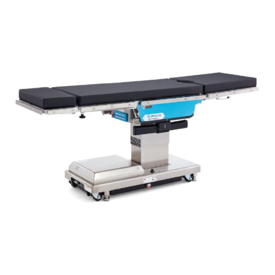
Operating Table MOT-VS500SK
Operator's Manual
This operating table is designed for medical operations. Using this operating table for any
other purpose other than this intended use may cause serious injury.
The operator and the person in charge of the maintenance of this operating table must read
this operator's manual thoroughly and understand the contents before operating, inspecting,
adjusting and maintaining it.
Keep this manual for reference in a place where is readily accessible.
MES-CK18-510-20EN Ver.1 2020-07-03
Advertisement
Table of Contents

Related Manuals for Mizuho MOT-VS500SK


Summary of Contents for Mizuho MOT-VS500SK
- Page 1 Operating Table MOT-VS500SK Operator’s Manual This operating table is designed for medical operations. Using this operating table for any other purpose other than this intended use may cause serious injury. The operator and the person in charge of the maintenance of this operating table must read this operator's manual thoroughly and understand the contents before operating, inspecting, adjusting and maintaining it.
-
Page 2: Table Of Contents
Table of contents Introduction ………………………………………………………… 1 This manual ……………………………………………………………………… 1 Intended use and this product ………………………………………………… 1 Accessories ……………………………………………………………………… 2 Safety precaution ………………………………………………… 3 Read thoroughly before using ………………………………………………… 3 Labeling ………………………………………………………………………… 7 Section Introduction ………………………………………………11 Main unit ………………………………………………………………………… 11 Control unit ………………………………………………………………………12 Cordless control unit (optional) …………………………………………………13 Foot switch (optional) ……………………………………………………………14... - Page 3 App.-1 Electromagnetic Compatibility …………………………………53 App.-2 Glossary ……………………………………………………………56...
-
Page 5: Introduction
. Introduction 1.1 This manual This manual contains information for safely and effectively using this product. Before operating this product, read this manual thoroughly to understand how to operate and inspect the product. Failure to follow these instructions could lead to serious injury. The safety information is categorized as per the following so that the contents of warnings and cautions, and the details of warnings and cautions which are labeled on the product may be comprehended. -
Page 6: Accessories
1.3 Accessories ■ Standard components and accessories Mattresses (for head, back and waist, and leg) Control unit Main unit Operator’s manual ■ Optional parts Foot switch Cordless control unit... -
Page 7: Safety Precaution
. Safety precaution 2.1 Read thoroughly before using Never perform the following when you use the product. Otherwise, damage to the operating table, electrical shock, and/or fire may occur. Any serious incident that has occurred in relation to the device should be reported to the manufacturer and the competent authority in which the user and / or patient is established. (1) Head plate and leg plate Do not step or sit on the head plate or the leg plate(s). - Page 8 (2) Control unit • Do not forcibly pull on the control unit cord. • Do not subject the control unit to strong shocks. The control unit may get WARNING damaged. (3) Base Do not place any objects on the base. An object may get caught and the operating table may get damaged.
- Page 9 • Make sure to inspect and maintain the operating table before and after use. The operating table may require replacement of the parts due to significant wear, deterioration, and/or breakage depending on the length of service and frequency of use. • For preventive maintenance and inspections, contact your distributor or Mizuho directly. ● Antistatic measure • Do not use the operating table on floors and/or with accessories that do not...
- Page 10 5. Wipe off the operating table with a clean dry cloth 15 minutes after disinfecting it. • Make sure to use Mizuho authorized disinfectants. The disinfectants are as shown below. a) Sodium hypochlorite 0.1% (halogen containing compound) b) Hypo Alcohol (iodine color removing agent) c) Chlorhexidine (chlorhexidine gluconate 0.5%)
-
Page 11: Labeling
2.2 Labeling The operating table is labeled at the locations shown as below. Before use, make sure to understand the contents of the labels. „ „ Warning and Caution labels (4)* (3)* *: Applied on both sides. (1) C656312□ (2) C643011□ (3) C653624□... - Page 12 „ „ Other labels (1/2) (20) (10)* (19) (11) (18) *: Applied on both sides. (12) (17) (13) (16) (15) (14) (10) C640029□ (11) C600020□ (12) C655648□ or C640030□ (13) C653515□ (14) C653516□ or C640031□ (16) C653513□ (17) C655002□ (15) C642002□ YYYY-MM-DD Made in ***...
- Page 13 „ „ Other labels (2/2) (21) (21) (21) (21) (21) (21) (22) (23) (24) (25) (26) (22) C646086□ (23) C646098□ (21) C653620□ (ASIA) or C646099□ or C646089□ (EU) or C646092□ or C646100□ (US) (25) PIN 360L6M2 (24) PIN 50005M2 (26) PIN 360L8M2...
- Page 14 Symbol mark for labeling ■ Symbol Description Label no. Indicates a possibility of injury or even death if operates the (1) (2) (3) (4) (5) (6) table without following the warning. (7) (9) General prohibition sign General mandatory action sign. Emergency stop (5) (8) (12) (15) (18) Refer to the operator’s manual...
-
Page 15: Section Introduction
. Section Introduction 3.1 Main unit Control unit Waist plate Leg plate(*2) Mattresses Head plate(*2) Back plate Liftup plate Head plate fixing handle (back of the leg plate) Leg plate release lever Auxiliary Head plate Side rail switch Slide cylinder flexing lever Emergency Head plate stop switch... -
Page 16: Control Unit
3.2 Control unit Power lamp Pilot lamp Battery lamp Reverse Trendelenburg: Trendelenburg: Head down Head up Lateral tilt: Left down Lateral tilt: Right down Back plate bending: Down Back plate bending: Up Table up Table down (Lock operating table) Slide foot Slide head Lift-up unit: Up Lift-up unit: Down... -
Page 17: Cordless Control Unit (Optional)
20 minutes. Switches other than the halted switch can be operated as usual. • If is pressed, the pilot lamp lights up for 3 seconds. • The cordless control unit can be set channels up to three. If you need the setting, contact your distributor or Mizuho. -
Page 18: Foot Switch (Optional)
3.4 Foot switch (optional) Lift: Up Lift: Down Trendelenburg: Reverse Lateral tilt: Lateral tilt: Head down Trendelenburg: Left down Right down Head up... -
Page 19: Operation
. Operation 4.1 Installation and battery charging „ „ Installing the operating table Move the operating table to a flat area. Check the battery lamp. If the battery lamp (orange) on the control unit flashes, battery charging is required. Battery lamp If the battery indicator shows empty (red), battery charging is required. POWER CORD POWER SWITCH BATTERY INDICATOR FOOT SWITCH BATTERY INDICATOR • Use the equipotential... - Page 20 „ „ Installation space This product requires the installation space shown as below. 2.5 m (98.4 in) or more 2.5 m (98.4 in) 2.5 m (98.4 in) or more or more 2.5 m (98.4 in) or more...
- Page 21 POWER CORD POWER SWITCH BATTERY INDICATOR FOOT SWITCH Power cord your distributor or Mizuho for a Power connector battery replacement. • The life-span for the battery varies greatly depending on When turn on the power switch, battery charging starts. operating conditions. The battery could degrade quicker While charging, the battery indicator sequentially flashes orange.
- Page 22 „ „ Attaching the control unit Align the connector with the guide and insert it into the receptacle properly. Insert the connector „ „ Detaching the control unit Turn the connector ring in the direction of the arrow until it stops.
- Page 23 „ „ Using the self-diagnostic function This product is equipped with an embedded self-diagnostic function capable of checking the communication status between the main unit and the control unit. Connect the power connector of the product and the medical grade outlet with the power cord. Press of the control unit.
- Page 24 „ „ Replacing the cordless control unit (optional) batteries Use a flat-blade screwdriver to remove the battery lid of the cordless control unit. Insert three AA batteries. NOTE • The average battery life- • Do not mix old and new batteries, nor different span is one year (depending battery types. CAUTION on usage conditions).
-
Page 25: Turning On/Off The Power
4.2 Turning on/off the power „ „ When the medical grade wall outlet is used „ Turning on the power NOTE • In an emergency or when Turn on the power switch on the base. turning off the power The power switch (green) and the battery indicator will be lighted on. completely, disconnect Power switch Battery indicator... - Page 26 „ „ When the battery is used „ Turning on the power NOTE • In an emergency or when When the power cord is not connected to the power turning off the power connector and the power switch on the base is turned off, completely, disconnect press of the control unit.
-
Page 27: Operating The Emergency Stop Switch
4.3 Operating the emergency stop switch In an emergency, you can stop operating table from moving by pressing the emergency stop switch. The emergency stop switch must be used only in an emergency. WARNING „ „ Operating in an emergency Press the emergency stop switch. -
Page 28: Fixing And Unfixing The Operating Table
4.4 Fixing and unfixing the operating table Fixing the operating table ■ Hold down and press NOTE The brake is activated to fix the operating table. Operations such as The operating table can be raising the tabletop will not operate until the fixing of the operating locked or unlocked once table is completed. - Page 29 „ „ Unfixing the operating table Do not unfix the operating table with a patient on it. The patient may fall from the operating table. WARNING Hold down and press for one second or more. The brake is released for unfixing the operating table. The operating table can be moved.
-
Page 30: Brake Release
4.5 Brake Release • Do not tilt the tabletop while the emergency brake release handle is in the “UNLOCK” position. WARNING The patient may fall from the operating table. • When the emergency brake release handle is returned, press to release the brake. -
Page 31: Tilting The Tabletop Laterally
4.6 Tilting the tabletop laterally When you tilt the tabletop laterally with a patient on the operating table, make sure to use the fixture for the accessory of the Mizuho operating table. WARNING The patient may fall from the operating table. „ „ Tilting to the left NOTE • The maximum angle achieved... -
Page 32: Trendelenburg
4.7 Trendelenburg When you operate the Trendelenburg operation with a patient on the operating table, make sure to use the fixture for the accessory of the Mizuho operating table. WARNING The patient may fall from the operating table. • When performing the head down operation, be careful that the head plate tip does not contact the floor. It CAUTION may get damaged. • When performing the head down operation, be careful... - Page 33 „ „ Trendelenburg (Head down) NOTE • The maximum angle of Hold down and press head down is 30° from the The tabletop moves to the head down position. level position. ° ° Head down position...
-
Page 34: Bending The Back Plate
4.8 Bending the back plate Keep your hands away from the following gaps during the operation of the table. Otherwise you may get injured. WARNING • Gap between the back plate and waist plate • Gap between the back plate gear and rack Back plate gear Back plate Waist plate... -
Page 35: Changing The Tabletop Height
4.9 Changing the tabletop height Leg plate Do not move down the table with the leg plate bent 90°. The tips of the leg plate may come in contact with the CAUTION base and get damaged. „ „ Moving up the tabletop NOTE • The maximum height from Hold down... -
Page 36: Sliding The Tabletop
4.10 Sliding the tabletop Keep your hands away from the gap of the frame during the operation of the table. Otherwise you may get injured. WARNING Do not slide the tabletop to the head direction from the standard center position with the leg plate bent. - Page 37 „ „ Sliding in the head direction NOTE • Maximum travel is 280 Hold down and press mm (11.0 in) in sliding from the center position of The tabletop slides in the head direction. the tabletop to the head direction. • The tabletop will stop at 280 mm Head ...
-
Page 38: Flexing Or Reflexing The Tabletop
4.11 Flexing or reflexing the tabletop Keep your hands away from the following gaps during the operation of the table. Otherwise you may get injured. WARNING • Gap between the back plate and waist plate • Gap between the back plate gear and rack Back plate gear Back plate Waist plate... - Page 39 Reflexing the tabletop ■ NOTE Hold down and press When the lift-up unit is up, The back plate bends upward and the waist plate turns to the reverse the reflexing position will Trendelenburg head down position. stop at the position the back plate is flexed at 45°.
-
Page 40: Change Height Of The Lift-Up Unit
4.12 Change height of the lift-up unit „ „ Moving up the lift-up unit NOTE • The highest moving-up Hold down and press position is 150mm (5.9in) The lift-up unit moves up. from the surface of the tabletop. • The lowest moving-down position is the same level of Move up the surface of the tabletop. -
Page 41: Bending The Leg Plate
4.13 Bending the leg plate • Do not place the tabletop in a reverse Trendelenburg position while the leg plate is bent down. CAUTION The tips of the leg plate may come in contact with the base and get damaged. •... - Page 42 Moving down the leg plate ■ NOTE • When the tabletop center Hold down and press point is slid 170 mm in the The leg plate moves down. head direction beyond the standard center position, the leg plate will move down only to 45°...
-
Page 43: Returning To Level
4.14 Returning to level Returning the tabletop to level position ■ NOTE Raising, sliding, and braking Hold down and press do not function. The tabletop from the Trendelenburg, lateral tilting, back plate bending, leg plate bending, flexing, and lift-up unit lifting positions will return to the level position. -
Page 44: Adjusting The Head Plate
4.15 Adjusting the head plate The head plate can be bent in 15° increments, to 4 different positions upward (maximum 60°) and to 6 different positions downward (maximum 90°). The head plate can also be detached. „ „ Bending the head plate • Make sure to tighten the head plate fixing handle securely. - Page 45 Attaching the head plate ■ NOTE The head plate can be • Make sure to tighten the head plate fixing handles attached by inserting it into securely. the reception hole of the WARNING If the head plate moves with the handles in a leg plate as a leg extension loosened state, the patient may get injured.
-
Page 46: Adjusting The Leg Plate
4.16 Adjusting the leg plate The leg plate is detachable. „ „ Detaching the leg plate The leg plate weighs 11 kg (24.3 lbs). Pay special attention when handling it. It may drop WARNING and cause damage or injury. Hold the both sides of the leg plate firmly and pull out the leg plate while pushing the leg plate release lever. - Page 47 Attaching the leg plate ■ • Make sure the leg plate is completely inserted. If the operating table is used without the leg plate WARNING being completely inserted into it, the patient may get injured by the leg plate being moved. •...
-
Page 48: Maintenance And Inspection
Make sure to inspect the items below before and after use. If there are any abnormalities, request your distributor or Mizuho for repairs. Otherwise it may cause WARNING problems during surgery. Inspect the items below. If there is any problem, request your distributor or Mizuho for repair. (1) Mattresses „ Before use • Check all the mattresses for any damage. - Page 49 (3) Table plates „ Before use • Check all the table plates for any damage. „ After use • Check all the table plates for any damage or dirt. (4) Control unit „ Before use • Press the switches on the control unit to see if all functions are working properly. (5) Power ON/OFF switch „...
-
Page 50: Periodic Replacement Parts
5.2 Periodic replacement parts Mizuho specifies that the following parts need to be periodically replaced for safety use. The replacement time is a rough standard. Earlier replacement may be required depending on the usage condition and/or usage frequency. Request your distributor or Mizuho for replacements. Control unit Battery Power cord Caster Brake rubber... -
Page 51: Specification
. Specification 6.1 Specification table Product name Operating Table MOT-VS500SK Highest 1090 mm (42.9 in) Elevation range Lowest 635 mm (25.0 in) Head up 30° Trendelenburg angle Head down 30° Left down 20° Lateral tilt angle Right down 20° 90° Back plate... - Page 52 Note 5: Excluding the side rail Note 6: Rough dimension Note 7: Company standard (in case that appropriate maintenance and inspection is done) Note 8: Based on Mizuho's own validation data Note 9: IEC 60601-1, Medical electrical equipment - Part1: General requirements for safety...
-
Page 53: External View
6.2 External view 632mm 240mm 468mm 62mm 475mm 585mm 2004mm 60° 150mm 90° 1033mm 500mm 1090mm 635mm 483mm... -
Page 54: Troubleshooting
. Troubleshooting „ „ Functions of the auxiliary switch • The auxiliary switch should be used only in an emergency. • Always watch movement of the operating table when you operate the auxiliary switch. Unlike the control CAUTION unit, the auxiliary switch has no function to halt the operation of the switches. -
Page 55: Before Contacting For Repairs
The lift-up unit is up. Move down the lift-up unit the lowest be moved past 45° at position. Page 36) the reflexing position. If the situation does not improve even if the above countermeasures are implemented, request repairs from your distributor or Mizuho. - Page 56 Maintenance by providers ■ For safety use of this product, make sure to perform the periodical inspection by Mizuho or the certified provider once a year. Inspections and maintenances by other than Mizuho or the certified provider could cause any adverse event such as deterioration of the performance and functions.
- Page 57 Normal operation may not be possible due to electromagnetic interference. Guidelines and manufacturer declaration – electromagnetic emissions The MOT-VS500SK is intended for use in the electromagnetic environment specified below. The customer or user of the MOT-VS500SK must ensure that it is operated in suchlike environments. Electromagnetic Compliance Electromagnetic environment – guideline...
- Page 58 Guidelines and manufacturer declaration – electromagnetic interference immunity The MOT-VS500SK is intended for use in the electromagnetic environment specified below. The customer or user of the MOT-VS500SK must ensure that it is operated in suchlike environments. Interference Electromagnetic IEC 60601 test level Compliance level immunity tests environment – guidelines Electrostatic discharge ±...
- Page 59 AM / FM radio broadcasts and TV broadcasts cannot be accurately and theoretically predicted. In order to confirm the electromagnetic environment caused by the fixed RF transmitter, it is desirable to consider an electromagnetic field survey. If the measured field strength exceeds the compliance level as specified above at the location where the MOT-VS500SK is used, the MOT-VS500SK should be observed to verify correct functionality. If abnormal performance is observed, additional measures may be necessary, such as re-orienting or relocating the MOT-VS500SK.
- Page 60 App.-2 Glossary Base The light-blue portion of the figure below. Flex The back plate is bent upward or downward, the waist plate moves to the head-up or the head-down position, and the entire tabletop moves to the "Center up" or "Center down." Lateral tilt Tabletop of the operating table moves to the left-down or the right-down position in the view from the head side.
- Page 61 Revision Record 2020-07-03 Ver.1 New release...
- Page 62 European authorized representative: Sales Agent Manufacturer: Emergo Europe B.V. MIZUHO Corporation Prinsessegracht 20, 2514 AP The Hague, The Netherlands 3-30-13 Hongo, Bunkyo-ku Tokyo 113-0033, Japan http://www.mizuho.co.jp...
Need help?
Do you have a question about the MOT-VS500SK and is the answer not in the manual?
Questions and answers