Mizuho MOT-VS700 Series Operator's Manual
Operating table
Hide thumbs
Also See for MOT-VS700 Series:
- Operator's manual (86 pages) ,
- Operator's manual (90 pages)
Table of Contents
Advertisement
Quick Links
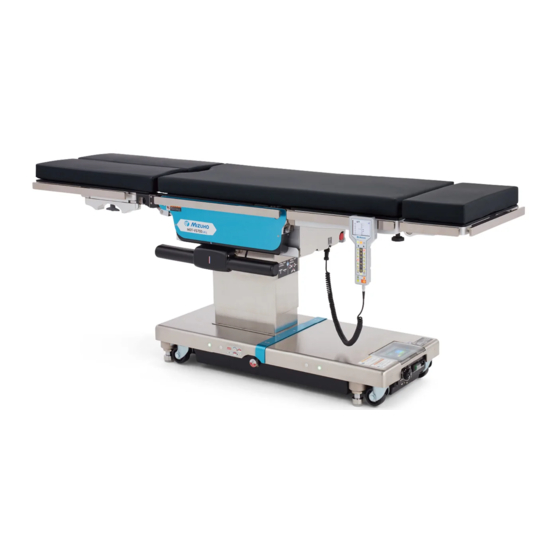
Operating Table MOT-VS700
Operator's Manual
This operating table is designed for medical operations. Using this operating table for any
other purpose other than this intended use may cause serious injury.
The operator and the person in charge of the maintenance of this operating table must read
this operator's manual thoroughly and understand the contents before operating, inspecting,
adjusting and maintaining it.
Keep this manual for reference in a place where is readily accessible.
MES-CK18-700-20EN Ver.2 2020-06-30
Advertisement
Table of Contents

Related Manuals for Mizuho MOT-VS700 Series


Summary of Contents for Mizuho MOT-VS700 Series
- Page 1 Operating Table MOT-VS700 Operator’s Manual This operating table is designed for medical operations. Using this operating table for any other purpose other than this intended use may cause serious injury. The operator and the person in charge of the maintenance of this operating table must read this operator's manual thoroughly and understand the contents before operating, inspecting, adjusting and maintaining it.
-
Page 2: Table Of Contents
Table of contents Introduction ………………………………………………………… 1 This manual ……………………………………………………………………… 1 Intended use and this product ………………………………………………… 1 Operation of this product ……………………………………………………… 2 Accessories ……………………………………………………………………… 2 Safety precaution ………………………………………………… 3 Read thoroughly before using ………………………………………………… 3 Labeling ………………………………………………………………………… 8 Section Introduction ………………………………………………12 Main unit …………………………………………………………………………12 Control unit ………………………………………………………………………13 Touch panel ………………………………………………………………………15... - Page 3 Version information of the software ……………………………………………64 LAN Port …………………………………………………………………………65 ………………………………………………………66 ………………………………………………………………66 External view ……………………………………………………………………68 Troubleshooting ……………………………………………………69 Before contacting for repairs ……………………………………72 App.-1 Electromagnetic Compatibility …………………………………74 App.-2 Glossary ……………………………………………………………77...
-
Page 5: Introduction
. Introduction 1.1 This manual This manual contains information for safely and effectively using this product. Before operating this product, read this manual thoroughly to understand how to operate and inspect the product. Failure to follow these instructions could lead to serious injury. The safety information is categorized as per the following so that the contents of warnings and cautions, and the details of warnings and cautions which are labeled on the product may be comprehended. -
Page 6: Operation Of This Product
1.3 Operation of this product The description of the operations written in this manual focuses mainly on those to be done by the control unit. For some operations operable only by the touch panel, however, those by the touch panel are described. 1.4 Accessories Standard components and accessories Mattresses (for head plate, back plate, waist plate) -
Page 7: Safety Precaution
. Safety precaution 2.1 Read thoroughly before using Never perform the following when you use the product. Any serious incident that has occurred in relation to the device should be reported to the manufacturer and the competent authority in which the user and / or patient is established. (1) Head plate and leg plate Do not step or sit on the head plate or the leg plate(s). - Page 8 Before lowering the table or placing it in a reverse Trendelenburg position, check if there are any devices CAUTION under the leg plates. If the leg plates come in contact with devices that are to be subjected to excessive force, the leg plate insertion shaft may be damaged.
- Page 9 (4) Touch panel Do not push the touch panel by any sharps such as a pen and a screw driver. The touch panel may get damaged. CAUTION Do not apply great impact or pressure to the touch panel. The touch panel may get damaged.
- Page 10 Make sure to inspect and maintain the operating table before and after use. The operating table may require replacement of the parts depending on the length of service and frequency of use. For preventive maintenance and inspections, contact your distributor or Mizuho directly. Antistatic measure...
- Page 11 4. As with step 3, disinfect the surfaces of the tables and side rails. 5. Wipe off the operating table with a clean dry cloth 15 minutes after disinfecting it. Make sure to use Mizuho authorized disinfectants. The disinfectants are as shown below. a) Sodium hypochlorite 0.1% (halogen containing compound) b) Sodium thiosulfate c) Chlorhexidine (chlorhexidine gluconate 0.5%)
-
Page 12: Labeling
2.2 Labeling The operating table is labeled at the locations shown as below. Before use, make sure to understand the contents of the labels. Warning and Caution labels Single Leg Section Fig. shows MOT-VS700UKIj with Double Leg Section (1) C655732 (2) C653624 (3) C656310 (Only MOT-VS700UKIj) (6) C656740... - Page 13 Other labels (1/2) (10) (11) (12) (13) (13) (12) (22) (14) (18) (13) (19) (20) (21) (34) Fig. shows MOT-VS700UKIj with Double Leg Section (17) (16) (15) (11) (10) C600020□ (12) C640018□ C640021□ (13) C655001□ C640019□ C640022□ (11) C655717□ (14) C657310□ C640020□...
- Page 14 Other labels (2/2) (23) (23) (23) (23) (23) (26) (27) MOT-VS700UIj (Fig. With Double Leg Section) (24) (25) (23) (23) (23) (23) (23) (28) (23) MOT-VS700UKIj (Fig. With Single Leg Section) (24) (25) (29) (33) Double Leg Section Single Leg Section (32) (31) (30) (23) C653620 (24) C646062 (25) C646063 (26) C646084 (27) C646061 (28) C646060 or C646080...
- Page 15 Symbol mark for labeling Symbol Description Label no. Indicates a possibility of injury or even death if operates the (1) (2) (3) (4)(6) (7) table without following the warning. General mandatory action sign. (6) (7) (5) (6) (15) (16) (19) Refer to the operators manual (22) General prohibition sign...
-
Page 16: Section Introduction
. Section Introduction 3.1 Main unit Mattresses Leg plate(*1 ・ 2) Back plate attaching/ Waist plate removing lever Lift-up plate Back plate(* Head plate(* Leg plate outstretching lever Leg plate attaching/ Head plate removing lever flexing lever Head plate Side rail fixing knob Control unit Emergency... -
Page 17: Control Unit
3.2 Control unit Brake status Battery level Status number Battery power status No.08 Err Warning for tipping over Panel Err Menu Display for touch panel failure Current position Control unit charge PILOT lamp request lamp Menu switch: Enter switch: Display table Set position position/Set memory Level/Center lamp... - Page 18 Menu switch When pressing on the control unit, the screen display will change as the following. Before you executing the lift-up or the beach-chair operation, select a respective screen with the menu switch. Usual screen Lift-up operation screen Current position Reverse orientation screen Beach chair operation screen Reverse Orientation...
-
Page 19: Touch Panel
3.3 Touch panel Main screen BACK-UP CONTROLS screen MEMORY FUNCTION screen Power source Position in operation WIRELESS SETTING screen Active memory mode Position set in the memory ON/OFF of the center position for each operation Language selection Battery indicator CAUTION screen BACK-UP CONTROLS screen (1/2) Slide: To leg Page... - Page 20 MEMORY FUNCTION screen Main screen Function button Settings of the position WIRELESS SETTING screen Main screen Mode selection IR code Bluetooth address Reset button CAUTION screen Main screen...
- Page 21 Error screen Go to the previous screen Go to the previous screen NOTE To prevent breakage, the operating table may automatically halt its operation if it detects any abnormality procedures after the operating table stopped, refer to Page 70. When two or more cautions/warnings exist, each error can be seen through the caution/warning screen. Pressing an error No.
-
Page 22: Foot Switch (Optional)
3.4 Foot switch (optional) Lift: Up Reverse Trendelenburg: Lateral tilt: (Fix table) Head up Right down Lift: Down Trendelenburg: Lateral tilt: Head down Left down... -
Page 23: Operation
. Operation 4.1 Installation of the operating table Installation space This product requires the installation space shown as below. 2.5 m (98.4 in) or more 2.5 m (98.4 in) 2.5 m (98.4 in) or more or more 2.5 m (98.4 in) or more Use the equipotential wire to ground the... -
Page 24: Connecting/Disconnecting The Control Unit
4.2 Connecting/Disconnecting the control unit Attaching the control unit To attach the control unit, connect it to the control unit connector on the operating table body. Insert the connector into the control unit connector on the operating table body along the guide on the control unit connector. - Page 25 Using the control unit wirelessly NOTE While being used wirelessly, The control unit can be detached from the main unit and used wirelessly. the control unit works on “Infrared mode” and “Bluetooth mode” are available for wireless the internal battery. The communication.
- Page 26 Using with the infrared mode The operating table does not function if the IR code displayed on the touch panel does not match with CAUTION that on the control unit. When there are plural operating tables in one room, using the same IR code for them possibly causes cross talk resulting in malfunction.
- Page 27 Press to match the IR code displayed on the touch NOTE panel with that on the control unit. The default IR code is "7". The IR code can be selected from 0 to 7 Press The IR code for the control unit is changed. Press Press to turn “BT Mode”...
- Page 28 Using in the Bluetooth mode Bluetooth wireless operation This function operates through the communication CAUTION via Bluetooth. Do not use this function if your facility’s rule bans wireless communication. Do not use the wireless communications if there are concerns that the medical devices will be affected by the effects of the radio waves when they are simultaneously being used.
- Page 29 Press and hold for 10 seconds. An IR code appears on the monitor screen of the control unit. Press Press to turn "BT Mode" to "ON". Press Press Press any operation button. A message "NOW CONNECTING" appears. After completion of NOTE communication setting between the operating table and the control If no operation is done on the...
- Page 30 Precautions on replacement of the control unit Before using a new control unit, be sure to initialize the Bluetooth address of the operating table by following the procedure below. Connect the new control unit to the operating table and turn on the power. Detach the control unit from the operating table.
- Page 31 Within 20 seconds, press of the control unit. If "SUCCESS" appeared and the address changed, replacement has completed. If "FAILURE" appeared, connection has failed. The battery of the control unit may be dead. CAUTION Charge the battery and retry the connection.
- Page 32 <Important> Using the control unit with other operating table (MOT-VS700) When using the current control unit with other MOT-VS700, be sure to cancel the Bluetooth information (paring) by following the procedure below. Turn "BT" to "ON" and tap "CLEAR", then wait for 12 seconds.
-
Page 33: Turning On/Off The Power
4.3 Turning on/off the power This procedure is different between the powers from the medical grade wall outlet and the battery. When the medical grade wall outlet is used Turning on the power NOTE In an emergency or when Turn on the power switch on the base. turning off the power The power switch green lights up, "AC MODE"... - Page 34 Turning off the power Turn off the power switch on the base. NOTE The power switch green lights off, and disappears on the display of If the power switch is turned off or the power cable is the control unit. disconnected, the battery OFF(〇) mode (Page 31) is...
- Page 35 When the battery is used Turning on the power Press of the control unit or the start switch on the right of the touch panel when no power cable is conn ected to the power connector or the power switch is turned off. "BATTERY MODE"...
- Page 36 urning off the powe Press of the control unit when no power cable is connected to the power connector or the power switch is turned off The touch panel and monitor light off.
-
Page 37: Charging The Battery
CAUTION Make sure to use the dedicated power cord with the "MIZUHO" logo. Before inserting the power cord into the power source connector, check that the To shut down the power completely, pull out the power cord from the medical grade outlet. -
Page 38: Operating The Emergency Stop Switch
4.5 Operating the emergency stop switch The emergency stop switch must be used only in an emergency. WARNING In an emergency, you can stop operating table from moving by pressing the emergency stop switch. Operating in an emergency In an emergency, press the emergency stop switch. NOTE The buzzer sounds and the operating table stops. - Page 39 Canceling operations After stopping the operation table, rotate the emergency stop switch in the direction of the arrow or pull it to release. The buzzer stops sounding. Emergency stop switch To reset the operating table to the original position in an emergency where, for example, an operator's hand is caught in a gap of the operating table, press the CAUTION switch on the control unit to move the table toward the reverse direction.
- Page 40 Fixing the operating table operating table. Press NOTE Operations such as raising completed, the brake lamp turns green. the tabletop will not operate is completed. Brake lamp After activating the brake, check that the WARNING If the operating table needs to be halted, press the emergency stop switch.
-
Page 41: Trendelenburg
4.7 Trendelenburg When you operate the Trendelenburg operation with a patient on the operating table, WARNING The patient may fall from the operating table. When performing the head down operation, be careful Head plate CAUTION fixing knob may get damaged. When performing the head down operation, be careful base. -
Page 42: Tilting The Tabletop Laterally
4.8 Tilting the tabletop laterally When you tilt the tabletop laterally with a patient on the operating table, make sure to WARNING The patient may fall from the operating table. NOTE Tilting to the left The maximum angle achieved in the left down position is Press 35°... -
Page 43: Tilting The Back Plate
4.9 Tilting the back plate Keep your hands away from the following gap during the operation of the table. You may get injured. WARNING Gap between the back plate and waist plate Gap between the back plate gear and rack Back plate gear Back plate Rack... -
Page 44: Changing The Tabletop Height
4.10 Changing the tabletop height Leg plate The tips of the leg plates may come in contact with the CAUTION base and get damaged. Moving up the tabletop NOTE Press the tabletop upper surface is The tabletop moves up. up to 1000 mm (39.4 in). Move up 1000 mm (39.4 in) -
Page 45: Sliding The Tabletop
4.11 Sliding the tabletop Keep your hands away from the gap of the frame during the operation of the table. WARNING Otherwise you may get injured. NOTE Sliding in the foot direction Maximum travel in sliding from the center position of Press the tabletop is as follows. -
Page 46: Tilting The Leg Plate
4.12 Tilting the leg plate Do not execute the reverse Trendelenburg with the leg plate lowered. The leg plate may come in contact with the base resulting in breakage. CAUTION Do not lower the tabletop with the leg plate lowered. The leg plate may come in contact with the base resulting in breakage. - Page 47 4.13 Keep your hands away from the following gaps during the operation of the table. You may get injured. WARNING Gap between the back plate and waist plate Gap between the back plate gear and rack Back plate gear Back plate Rack Waist plate Flexing the tabletop...
-
Page 48: Change Height Of The Lift-Up Unit (Mot-Vs700Ukij Only)
4.14 Change height of the lift-up unit (MOT-VS700UKIj only) Moving up the lift-up unit NOTE The highest moving-up position Press is 150 mm (5.9 in) from the surface of the tabletop. Press The lowest moving-down position is the same level of The lift-up unit moves up. -
Page 49: Beach Chair
4.15 Beach chair Keep your hands away from the following gap during the operation of the table. You may get injured. WARNING Gap between the back plate and waist plate Back plate Waist plate Beach chair Press Press The operating table gets into the beach chair position. -
Page 50: Operating Memory
4.16 Operating memory By registering an arbitrary position of the operating table into the memory, the operating table can get to the registered position easily. Registering a position of the tabletop NOTE The number of operations Registering with the control unit to be registered is up to 3. - Page 51 Registering with the touch panel Put the operating table into a position to be registered. Press "MEMORY SELECT" several times until a memory in which you wish to register appears. If the memory number you wish to register appeared, press "SET".
- Page 52 Reproducing a registered positio NOTE In the reverse mode, no Reproducing with the control uni memory can be operated Press several times until a memory in which you wish NOTE to register appears To close the memory mode, press Press A function button necessary for reproducing the position lights up NOTE Does not light up when being...
- Page 53 Repeat step 3 until all the function buttons lit off. When the tabletop is moved to the target position, the number of "MEMORY POSITION" turns blue. Reproducing with the touch panel Press "MEMORY SELECT" several times until a memory NOTE that you want to use appears.
-
Page 54: Reverse Mode
4.17 Reverse mode When a patient is placed in a reverse head-to-foot orientation, the reverse mode allows the operation with reference to the patient head. The head plate can be attached to the back plate and the Single Leg Section (reverse mode) only. WARNING Allowable load: 135kg (298lbs) Activating the reverse mode... - Page 55 Deactivating the reverse mode Select and select the reverse mode (Reverse NOTE Orientation). The reverse mode is kept even after the power is turned Press off. Deactivate the reverse The reverse mode is deactivated. mode, if unnecessary. The reverse mode deactivates when using the Double Leg section.
-
Page 56: Returning To Level
4.18 Returning to level Returning the tabletop to level position NOTE The lifting, sliding, and braking Press functions do not work. The tabletop executes Trendelenburg, lateral tilt, back plate bending, only), then returns to the level position. -
Page 57: Adjusting The Head Plate
4.19 Adjusting the head plate different positions downward (maximum 90°). The head plate can also be detached. the patient may get injured. WARNING The head plate weighs 6 kg (13 lbs). Pay special attention when handling it. It may drop and cause damage or injury. Flexing the head plate Head plate flexing lever... - Page 58 Attaching the head plate If the head plate moves, the patient may get injured. WARNING The head plate can be attached to the back plate and the Single Leg Section (reverse mode) only. Hold both sides of the head plate, align and insert the insertion shafts of the head plate into the insertion holes on the back plate or the Single Leg Section (in the reverse mode).
-
Page 59: Attaching/Detaching The Back Plate
4.20 Attaching/detaching the back plate The back plate is detachable. Detaching the back plate Make sure to check that the back plate is inserted securely. If the back plate moves, the patient may WARNING get injured. The back plate weighs 8 kg (18 lbs). Pay special attention when handling it. - Page 60 Attaching the back plate Make sure to check that the back plate is inserted securely. If the back plate moves, the patient may WARNING get injured. The back plate weighs 8 kg (18 lbs). Pay special attention when handling it. It may drop and cause damage or injury.
-
Page 61: Adjusting The Double Leg Section (Optional)
4.21 Adjusting the Double Leg Section (optional) The Double Leg section is outward stretchable, and detachable. Outstretching the leg plates The leg plate can be opened outward up to 42 degrees (centering around Rotate the leg plate opening knob on the lower part of the leg plate in the direction shown by the arrow to release the lock of the leg plate. - Page 62 Rotate the leg plate opening knob on the lower part of the leg plate in the direction shown by the arrow to lock the leg plate.
- Page 63 Detaching the leg plates Do not sit on or lean against the tip of the leg plate. Otherwise, tipping over and/or injuries may occur. WARNING After attaching the leg plate, always check that the leg plate is inserted securely by pushing the leg plate back and forth.
-
Page 64: Attaching/Detaching The Single Leg Section (Optional)
4.22 Attaching/detaching the Single Leg Section (optional) The Single Leg Section is detachable. Detaching the leg plate Do not sit on or lean against the tip of the leg plate. Otherwise, tipping over and/or injuries may occur. WARNING After attaching the leg plate, always check that the leg plate is inserted securely by pushing the leg plate back and forth. - Page 65 Attaching the leg plate leg plates with the insertion holes, and insert the leg plates. Check that the leg plate is inserted securely by pulling the leg plate.
-
Page 66: Maintenance And Inspection
Mizuho for repairs. Otherwise it may cause WARNING problems during surgery. Inspect the items below. If there is any problem, request your distributor or Mizuho for repair. (1) Mattresses Before use Check all the mattresses for any damage. - Page 67 (3) Table plates Before use Check all the table plates for any damage. After use Check all the table plates for any damage or dirt. (4) Control unit Before use Press the switches on the control unit to see if all functions are working properly. (5) Oil leakage Before and after use (6) Battery...
-
Page 68: Periodic Replacement Parts
5.2 Periodic replacement parts Mizuho specifies that the following parts need to be periodically replaced for safety use. The replacement time is a rough standard. Earlier replacement may be required depending on the usage condition and/or usage frequency. Request your distributor or Mizuho for replacements. -
Page 69: Lan Port
The operating table does not support connections with any genenal external devices or systems. Connections with devices or systems other than those allowed by MIZUHO are not guaranteed to work. When you desire to connect with external devices or network, please contact us. - Page 70 Product name Operating Table MOT-VS700UI Operating Table MOT-VS700UKI Highest 1000 mm ± 10 mm (39.4 in) Elevation range Lowest 520 mm ± 10 mm (20.5 in) Head down 40° ± 2° Trendelenburg angle Head up 30° ± 2° Right down 35°...
- Page 71 Note 5: Excluding the side rail Note 6: Rough dimension Note 7: Company standard (in case that appropriate maintenance and inspection is done) Note 8: Based on Mizuho's own validation data Note 9: IEC 60601-1, Medical electrical equipment - Part1: General requirements for safety...
-
Page 72: External View
6.2 External view (Unit : mm) MOT-VS700UKIj With Double Leg Section With Single Leg Section 2005 2124 MOT-VS700UIj With Double Leg Section With Single Leg Section 2124 2005 1133 1133... -
Page 73: Troubleshooting
. Troubleshooting When the brake cannot be released Do not tilt the tabletop while the emergency brake release dial is in the "UNLOCK" position. CAUTION The patient may fall from the operating table. If you put back the emergency break release handle, press on the control unit to release the break. - Page 74 Use the touch panel or the infrared remote controller. 22. Low Battery The battery level is low. Charge the battery. The sensor for up and down has any abnormality. Request repairs 24. Table Up Potentiometer from your distributor or Mizuho.
- Page 75 Possible cause and measures The sensor for Trendelenburg and lateral tilt has any abnormality. 25. Tilt Sensor Request repairs from your distributor or Mizuho. The sensor for the back plate has any abnormality. Request repairs 27. Back Potentiometer from your distributor or Mizuho.
-
Page 76: Before Contacting For Repairs
Turn the power switch off and disconnect the power cord from the medical grade outlet. Place an "Out of Order" or "Do Not Use" sign on the operating table. providers. Make sure to contact your distributor or Mizuho for maintenance or repairs. WARNING Do not disassemble the operating table. - Page 77 For request for the periodical inspection, contact your distributor or Mizuho. Warranty MIZUHO Corporation will repair defective parts of this product without charge for one year from the date of delivery/installment except for cases of damage caused by a third party’s repair, act of nature, improper use or...
-
Page 78: App.-1 Electromagnetic Compatibility
App.-1 Electromagnetic Compatibility Install and operate according to the EMC information provided in this manual. This can result in increased emissions and reduced immunity. WARNING Do not use it adjacent to or stacked with other equipment. Normal operation may not be possible due to electromagnetic interference. Before using other medical electronic devices (especially life support devices) to be used together, make sure that they will not malfunction due to electromagnetic interference. - Page 79 Guidelines and manufacturer declaration – electromagnetic interference immunity The customer or user of the MOT-VS700 must ensure that it is operated in suchlike environments. Interference Electromagnetic IEC 60601 test level Compliance level immunity tests environment – guidelines Electrostatic discharge ± 8 kV ±...
- Page 80 Guidelines and manufacturer declaration – electromagnetic interference immunity (continuation) Conducted disturbances 150 kHz to 80 MHz 150 kHz to 80 MHz Portable and mobile RF induced by radiated RF communications equipment IEC 61000-4-6 (radio devices, incl. antennas or ISM frequencies ISM frequencies cables) should be used no closer to any part of the MOT-VS700...
-
Page 81: App.-2 Glossary
App.-2 Glossary Base The back plate is bent upward or downward, the waist plate moves to the head-up or the head-down position, and the entire tabletop moves to the "Center up" or "Center down." Lateral tilt Tabletop of the operating table moves to the left-down or the right-down position in the view from the head side. - Page 82 Revision Record May 11.2020 Ver.1 New release June 30.2020 Ver.2 Revision...
- Page 83 European authorized representative: Sales A gent Manufacturer: Emergo Europe B.V. Prinsessegracht 20, 2514 A P The Hague, T he Netherlands 3-30-13 Hongo, Bunkyo-ku Tokyo 113-0033, Japan http://www.mizuho.co.jp...
Need help?
Do you have a question about the MOT-VS700 Series and is the answer not in the manual?
Questions and answers