Advertisement
Quick Links
Advertisement

Related Manuals for Mizuho MOT-3602


Summary of Contents for Mizuho MOT-3602
- Page 1 Operating Table Operator's Manual MOT-3602 MES-CK18-100-10EN Ver.6 2023-07-14...
- Page 2 Page 1 TABLE OF CONTENTS Title Page WARRANTY ·················································································································································· 3 EQUIPMENT LABELS ·································································································································· 4 SAFETY & HEALTH SYMBOLS ···················································································································· 5 TABLE SPECIFICATIONS ····························································································································· 7 SPECIAL USER ATTENTION ························································································································ 9 SECTION I INTRODUCTION ··················································································································· 16 1-1. General ········································································································································· 16 1-2. Power Requirements ···················································································································· 16 1-3.
- Page 3 Page 2 TABLE OF CONTENTS (continued) Title Page SECTION IV ELECTROMAGNETIC EMISSIONS ···················································································· 38 Although current at the time of publication, MIZUHO’s policy of continuous development makes this manual subject to change without notice.
- Page 4 Page 3 WARRANTY MIZUHO Corporation will repair defective parts of this product without charge for one year from the date of delivery/installment except for cases of damage caused by a third party's repair, act of nature, improper use or damage on purpose. All other warranty terms and conditions are subject to...
- Page 5 Page 4 EQUIPMENT LABELS C642002 YYYY-MM-DD Made in ***...
- Page 6 Page 5 SAFETY & HEALTH SYMBOLS Used On Used In Symbol Description Product Manual ○ ○ NOTE Indicates important facts or helpful hints ○ ○ General warning sign (WARNING, CAUTION) ISO 7010-W001 ○ Type B applied part IEC 60417-5840 IPX4 ○...
- Page 7 Page 6 SAFETY & HEALTH SYMBOLS Used On Used In Symbol Description Product Manual ○ General prohibition sign ISO 7010-P001 Blue ○ General mandatory action sign ISO 7010-M001 ○ Emergency stop IEC 60417-5638 ○ Protective earth (ground) IEC 60417-5019 ○ Defibrillation-proof Type B applied part IEC 60417-5841...
- Page 8 Page 7 TABLE SPECIFICATIONS 75 mm 240 mm 464 mm 475 mm 585 mm TOP VIEW 396 mm 2000 mm 60° 500 mm 150 mm 71 mm 90° 1100 mm 620 mm 483 mm 1033 mm FRONT VIEW SIDE VIEW Electrical Specifications Power Requirements: 100 - 240 VAC, 50 - 60 Hz, 400 VA...
- Page 9 Page 8 TABLE SPECIFICATIONS Mechanical Specifications Maximum Lifting Capacity: 450 kg Maximum Articulating Capacity: 360 kg The height and width to be able to pass by: Height 10 mm/Width 80 mm (0.4m/s±0.1m/s)
- Page 10 Page 9 SPECIAL USER ATTENTION Prior to use, all personnel that may operate this In general, common sense will dictate when there is table must be instructed in the correct opera- a potential hazard. tional procedures. This table is designed for use by trained and qualified personnel for human The following precautions should be reviewed medical purposes only.
- Page 11 Protective earth. NOTE Power Cord has to be used the one operating table built-in which has a logotype of MIZUHO. self-diagnosis function to check if the operating table and control unit work properly. WARNING Please don't position the surgical table 1.
- Page 12 Page 11 SPECIAL USER ATTENTION NOTE WARNING When the red light starts to blink (indi- Please confirm that the operating table cating low power in battery) the table is fixed stably after applying the brakes. will operate for approximately 5 contin- uous minutes, typically long enough to ...
- Page 13 Page 12 SPECIAL USER ATTENTION NOTE NOTE With an evenly distributed patient If the leg section is below horizontal, weight load, all table positioning func- slide toward head is limited to 195 mm tions will operate smoothly and quietly from center. with a patient weight of up to 360 kg.
- Page 14 Page 13 SPECIAL USER ATTENTION NOTE WARNING The table top must be centered or slid Ensure that the Leg and Back sections toward the foot end for the Beach Chair are properly engaged and secured to function to operate. pins before use to prevent injury. CAUTION NOTE Please use the emergency switch at the...
- Page 15 Tag which indicates that a mattress is Accessories and products not furnished by MIZUHO have not been tested for an applied part and is made by proper performance and safety. Such MIZUHO is attached on a mattress.
- Page 16 SECTION I HYDRAULIC SYSTEM MECHANICAL TABLE SECTION II ADJUSTMENTS HYDRAULIC SECTION III TROUBLESHOOTING SECTION IV ELECTRICAL SYSTEM ELECTRICAL SECTION V TROUBLESHOOTING Maintenance Manual can be obtained only by the person who has had the service training of MIZUHO.
- Page 17 Page 16 SECTION I INTRODUCTION MATTRESS MATTRESS MATTRESS Tokyo, Japan PIN 50005M2 SEAT SECTION KIDNEY SECTION BACK 671DU03 SECTION HEAD SECTION SECTION Tokyo, Japan 671DU04 PIN 360L6M2 562GU01 Tokyo, Japan PIN 360L8M2 SIDE RAIL LEG SECTION RELEASE LEVER (RECESSED) HEAD SECTION LOCKING KNOB PENDANT EMERGENCY...
- Page 18 Page 17 SECTION I INTRODUCTION AC100 -240 V POWER 1-3. Pendant Control Unit ON INDICATOR LIGHT (GREEN) The hand-held pendant control unit (figure 1-3) has REVERSE TRENDELENBURG TRENDELENBURG a non-slip rubber cover which assures a positive LATERAL TILT LATERAL TILT grip during use.
- Page 19 Page 18 SECTION I INTRODUCTION 1-4. Floor Lock/Brake System The floor lock/brake system consists of four self-leveling, hydraulic brake cylinders which raise and support the table base off from the casters. Press the TABLE UP button on the pendant control to set the table’s brakes.
- Page 20 Protective earth. culty to disconnect the Equipment by Power Cord has to be used the one plug or appliance outlet. which has a logotype of MIZUHO.
- Page 21 Page 20 SECTION II OPERATION 2-3. Battery Operation 2-5. Charging the Battery a. Make sure the Main Power Switch indicator light, Batteries should be charged: When the table is placed into initial service on the electrical panel, are OFF. See figure 2-2. If ...
- Page 22 Page 21 SECTION II OPERATION WARNING If the table is stored for a period greater than 6 months, the batteries should be removed and stored in a dry, clean condition at a storage temperature of POWER CORD POWER SWITCH BATTERY INDICATOR FOOT SWITCH 68°...
- Page 23 Page 22 SECTION II OPERATION Press the ENERGIZE button and then the BRAKE OPERATOR’S 180° POSITION UNLOCK button on the pendant control to release the four self-leveling brake feet in order to move the table. See figure 2-6. The brake delay circuit auto- matically retracts the brake system.
- Page 24 Page 23 SECTION II OPERATION Prior to unlocking brakes, check for ob- REVERSE TRENDELENBURG structions on the floor that might pre- TRENDELENBURG vent the table from moving smoothly to new location. Relock the brakes imme- diately once the final position is reached and before commencing sur- ENERGIZE gery.
- Page 25 Page 24 SECTION II OPERATION d. Back Section To raise the back section, press CAUTION the ENERGIZE button and then the BACK UP but- ton (figure 2-9). The back section will raise up to 90° The combination of minimum elevation (top all the way down), extreme above horizontal.
- Page 26 Page 25 SECTION II OPERATION To move the table top toward the foot end, press the ENERGIZE button and then the SLIDE FOOT but- ton. From center position, the top will slide up to 335 mm. Slide function will stop and RETURN CTR In- LEG UP LEG DOWN dicator will illuminate when table is centered.
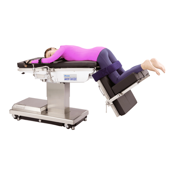
- Page 27 Page 26 SECTION II OPERATION i. Kidney Lift To raise the built-in kidney lift, k. Beach Chair To place the top in the beach press the ENERGIZE button and then the KIDNEY chair position from a level position, press the UP button (figure 2-14).
- Page 28 Page 27 SECTION II OPERATION b. In the event of either a power failure or a problem 2-7. Emergency Switch with the hand-held pendant control, the table can be operated using the emergency back-up switches. Emergency switch is above the control box con- Simply push the desired emergency switch in the nector.
- Page 29 Page 28 SECTION II OPERATION 2-9. Emergency Brake Release SERVICE ACCESS COVER In case of a power failure or an electrical problem within the table, the emergency brake release sys- tem can be used to move the table. The control knob for this function is located on the side of the table base and is identified by an EMERGENCY BRAKE BRAKE (4)
- Page 30 ONLY. Do not reverse the patient on the table without first consulting with MIZUHO. Two locking knobs are located on the inside of the Figure 2-23. Leg Section Removal leg section for securing the head section.
- Page 31 1 cm apart from 1. Attach a mattress to table board. a side rail so that a patient dose not A mattress which is made by MIZUHO and is touch on side rails (metal). exclusive use of this table is used. (Refer to the following Notes) ...
- Page 32 50005M2 360L6M2 360L8M2 Mattress's shape is suitable for each table board. Tag which indicates that a mattress is an applied part and is made by MIZUHO is attached on a mattress. 50005M2 360L6M2 360L8M2 Figure 2-26. Tag of Mattress...
- Page 33 The following preventive maintenance checks and services are recommended to ensure the servicea- The following inspections should be done before bility and proper operation of your MIZUHO Surgical and after each use of the table. Table, and should only be performed by qualified MIZUHO trained personnel.
- Page 34 Page 33 SECTION III MAINTENANCE Using a clean, dry, lint-free cloth, wipe the pads to 3-3. Cleaning Recommendations remove all moisture. WARNING Repeat the steps to clean the bottom of the each pad. Personal injury to patient or staff may result from a lack of proper mainte- nance of this equipment.
- Page 35 Page 34 SECTION III MAINTENANCE b. Disinfection The following procedure should be followed when disinfecting an operating table. 1. Remove all table pads from the operating ta- ble. 2. Apply a proper quantity of disinfectant on the clean and lint-free cloth, and wipe the top and sides and bottom of the pads with the cloth.
- Page 36 2red Replacement and reconnect of battery and fuse and reset of breaker have to be performed by trained service staff of MIZUHO. If corrective actions for the following symptoms are necessary, be sure to contact an agency of MIZUHO.
- Page 37 Page 36 SECTION III MAINTENANCE SURGICAL TABLE MAINTENANCE MATRIX Component 1 Year 2 Years 5 Years 7 Years Lateral Tilt Housing Bolts Side Rails & Gravity Stops Velcro Hydraulic Oil Level A.C. Power Cord Self-Leveling Brake Pad Lubricate Casters Lubricate Elevation Column Tighten X-Ray Top Standoffs &...
- Page 38 3-7. Disposal Instructions thorized disassembling cause The end of the useful life for the MIZUHO electric shock or malfunction. Surgical Table is when this product can no Please contact your local distributor or longer be ser-viced to comply with MIZUHO standards as deter-mined by a MIZUHO authorized manufacturer for maintenance or repair.
- Page 39 Page 38 SECTION IV ELECTROMAGNETIC EMISSIONS Medical Electrical Equipment needs special precautions regarding EMC and needs to be installed and put into service according to the EMC information provided in this manual. Portable and mobile RF communications equipment can affect Medical Electrical Equipment. The use of Accessories, transducers, and cables other than those specified, with the exception of transducers and cables sold by the Manufacturer of this device as replacement parts for internal components, may result in increased Emissions or decreased Immunity of the 3602 Surgical Table.
- Page 40 Page 39 SECTION IV ELECTROMAGNETIC EMISSIONS RECOMMENDED SEPARATION DISTANCES BETWEEN PORTABLE AND MOBILE RF COMMUNICATIONS EQUIPMENT AND THE 6300 SURGICAL TABLE The 3602 Surgical Table is intended for use in an electromagnetic environment in which radiated RF dis- turbances are controlled. The customer or the user of the 3602 Surgical Table can help prevent electromag- netic interference by maintaining a minimum distance between portable and mobile RF communications equipment (transmitters) and the 3602 Surgical Table as recommended below, according to the maximum output power of the communications equipment.
- Page 41 Page 40 SECTION IV ELECTROMAGNETIC EMISSIONS GUIDANCE AND MANUFACTURER’S DECLARATION – ELECTROMAGNETIC IMMUNITY The 3602 Surgical Table is intended for use in the electromagnetic environment specified below. The cus- tomer or the user of the 3602 Surgical Table should assure that it is used in such an environment. Electromagnetic environ- Immunity test IEC 60601 test level...
- Page 42 Page 41 SECTION IV ELECTROMAGNETIC EMISSIONS GUIDANCE AND MANUFACTURER’S DECLARATION – ELECTROMAGNETIC IMMUNITY The 3602 Surgical Table is intended for use in the electromagnetic environment specified below. The cus- tomer or the user of the 3602 Surgical Table should assure that it is used in such an environment. Electromagnetic environment –...
- Page 43 Sales Agent EMERGO EUROPE MIZUHO Corporation Westervoortsedijk 60 6827 AT Arnhem, The Netherlands 3-30-13 Hongo, Bunkyo-ku Tokyo 113-0033, Japan https://www.mizuho.co.jp...
Need help?
Do you have a question about the MOT-3602 and is the answer not in the manual?
Questions and answers