Table of Contents
Advertisement
Quick Links
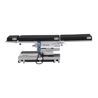
Operating Table MOT-5602BW
Operator's Manual
This operating table is designed for medical operations. Using this operating table for any
other purpose other than this intended use may cause serious injury.
The operator and the person in charge of the maintenance of this operating table must read
this operator's manual thoroughly and understand the contents before operating, inspecting,
adjusting and maintaining it.
Keep this manual for reference in a place where is readily accessible.
MES-CK18-450-10EN Ver.6 2023-07-14
Advertisement
Table of Contents

Related Manuals for Mizuho MOT-5602BW


Summary of Contents for Mizuho MOT-5602BW
- Page 1 Operating Table MOT-5602BW Operator's Manual This operating table is designed for medical operations. Using this operating table for any other purpose other than this intended use may cause serious injury. The operator and the person in charge of the maintenance of this operating table must read this operator's manual thoroughly and understand the contents before operating, inspecting, adjusting and maintaining it.
-
Page 2: Table Of Contents
Table of contents Introduction ………………………………………………………… 1 This manual ……………………………………………………………………… 1 Intended use and this product ………………………………………………… 1 Accessories ……………………………………………………………………… 2 Safety precaution ………………………………………………… 3 Read thoroughly before using ………………………………………………… 3 Labeling ………………………………………………………………………… 8 Section Introduction ………………………………………………12 Main unit …………………………………………………………………………12 Hand controller …………………………………………………………………13 Foot switch (optional) ……………………………………………………………14 Operation ……………………………………………………………15 Installation and battery charging ………………………………………………15... -
Page 3: Introduction
. Introduction 1.1 This manual This manual contains information for safely and effectively using this product. Before operating this product, read this manual thoroughly to understand how to operate and inspect the product. Failure to follow these instructions could lead to serious injury. The safety information is categorized as per the following so that the contents of warnings and cautions, and the details of warnings and cautions which are labeled on the product may be comprehended. -
Page 4: Accessories
1.3 Accessories „ Standard components and accessories Flame-Retardant and Waterproof Pads (SUSANO Pad) (for Head Section Type A, Back and Seat Section Type C, Double Leg Section Type B) Hand controller Main unit Power cord Operator’s manual „ Optional Foot switch... -
Page 5: Safety Precaution
. Safety precaution 2.1 Read thoroughly before using In using this product, carefully read the following warnings and cautions, and make sure to observe them. Any serious incident that has occurred in relation to the device should be reported to the manufacturer and the competent authority in which the user and/or patient is established. - Page 6 (2) Hand controller • Do not forcibly pull the hand controller cord. • Do not subject the hand controller to strong shocks. The hand controller may get WARNING damaged. (3) Upper area of the base cover Do not put any object on the cover. When the table moves downward, or into the CAUTION Trendelenburg or the lateral tilt position, the slide...
- Page 7 • Attach the table pads straight along the Velcro fastenings from the edges. Attach especially long table pads while holding them with your hands so that the surfaces CAUTION do not get wrinkled. If the table pads rise up or buckle, they may get deformed or damaged.
- Page 8 • Make sure to inspect and maintain the operating table before and after use. The operating table may require replacement of the parts due to significant wear, deterioration, and/or breakage depending on the usage period and frequency of use. • For preventive maintenance and inspections, contact your distributor or Mizuho directly. ● Antistatic measure •...
- Page 9 4. As with step 3, disinfect the surfaces of the tables and side rails. 5. Wipe off the operating table with a clean dry cloth within 15 minutes after disinfecting it. • Make sure to use Mizuho authorized disinfectants. The disinfectants are as shown below. a) Sodium hypochlorite 0.1% (halogen containing compound) b) Hypo Alcohol (iodine color removing agent) c) Chlorhexidine (chlorhexidine gluconate 0.5%)
-
Page 10: Labeling
The operating table is labeled at the locations shown as below. Before use, make sure to understand the contents of the labels. Warning and Caution labels (3)* (4)* *: Applied on both sides. (1) C655650 (2) C655608 (3) C653624 (4) C655732 (5) C655649 (6) C656740 (7) C655803... - Page 11 Other labels (1/2) (10)* (11)* (19) (16) (12)* (13) (14) (15) (17) (18) *: Applied on both sides. (10) C600516 (11) C655646 (12) C600020 (13) C655648 (14) C653515 (15) C653516 (16) C600559 (17) C653513 (18) C642002 YYYY-MM-DD (19) C655683...
- Page 12 Other labels (2/2) (20) (20) (20) (20) (20) (21) (22) (23) (27) (24) (25) (26) (20) C653620 (21) C646067 (ASIA) (22) C655692 (ASIA) (23) C655691 (ASIA) C646070 (EU) C655690 (EU) C655689 (EU) C646073 (US) C655687 (US) C655686 (US) (24) PIN 558K5M1 (25) PIN 558K6M7 558K5M1 558K6M7...
- Page 13 „ Symbol mark for labeling Symbol Description Label no. Indicates a possibility of injury or even death if operates the (1) (2) (3) (4) (5) (6) table without following the warning (7) (8) General prohibition sign General mandatory action sign Emergency stop Refer to the operator's manual (6) (9) (13) (18) (19) Indicates AC power supply...
-
Page 14: Section Introduction
. Section Introduction 3.1 Main unit Emergency stop switch Hand controller Table pads Leg section (*1) Seat section Back section Head section (*1) Leg section flexing lever Leg section fixing handle Side frame Side rail Slide cylinder Head section Column flexing lever Head section fixing handle Base... -
Page 15: Hand Controller
3.2 Hand controller MOT-5602BW Power lamp Pilot lamp Battery lamp PILOT POWER BATT. REV. TREND. TREND. Reverse Trendelenburg: Trendelenburg: Head down Head up TILT LEFT TILT RIGHT Lateral tilt: Left down Lateral tilt: Right down BACK UP BACK DOWN Back section down... -
Page 16: Foot Switch (Optional)
3.3 Foot switch (optional) Table up Table down Trendelenburg: Reverse Lateral tilt: Lateral tilt: Head down Trendelenburg: Left down Right down Head up... -
Page 17: Operation
• When moving this product, carry it out with two or more persons. Equipotential terminal Equipotential wire „ Installing the operating table Move the operating table to a flat area. Check the battery lamp. If the battery lamp (orange) on the hand controller flashes, battery charging is required. MOT-5602BW PILOT POWER BATT. Battery lamp REV. TREND. TREND. (Orange・flash) TILT LEFT TILT RIGHT BACK UP... - Page 18 „ Installation space This product requires the installation space shown as below. 2.5m (98.43 in) or more 2.5m (98.43 in) 2.5m (98.43in) or more or more 2.5m (98.43in) or more...
- Page 19 • The operating table battery replacement time is about 2 years. Once it reaches its replacement time, request your distributor or Mizuho for a battery replacement. • The life-span for the battery varies greatly depending When turning on the power switch, battery charging starts.
- Page 20 „ Attaching the hand controller Align the connector with the guide and insert it into the receptacle properly. Insert the connector „ Detaching the hand controller Turn the connector ring in the direction of the arrow until it stops. Pull up the connector. 2.
- Page 21 „ Using the self-diagnostic function This product is equipped with an embedded self-diagnostic function capable of checking the communication status between the main unit and the hand controller. Connect the power connector of the product and the medical grade outlet with the power cord. Press of the hand controller.
-
Page 22: Turning On/Off The Power
Power switch (Green・light up) Press on the hand controller. ON/OFF The power lamp (green) on the hand controller lights up and the power is turned on. MOT-5602BW PILOT POWER BATT. REV. TREND. TREND. Power lamp... - Page 23 ON/OFF The power lamp (green) on the hand controller goes out. controller, the battery power will be turned on. MOT-5602BW PILOT POWER BATT. REV. TREND. TREND. Power lamp TILT LEFT TILT RIGHT (Green・go out)
- Page 24 ON/OFF The power lamp (green) and battery lamp (orange) on the hand controller and battery indicator light up, and the power is turned on. MOT-5602BW PILOT POWER BATT. REV. TREND. TREND. Power lamp (Green・light up)/...
-
Page 25: Operating The Emergency Stop Switch
4.3 Operating the emergency stop switch In an emergency, you can stop the operating table from moving by pressing the emergency stop switch. The emergency stop switch must be used only in an emergency. WARNING „ Operating in an emergency NOTE Press the emergency stop switch. -
Page 26: Fixing And Unfixing The Operating Table
4.4 Fixing and the operating table Fixing the operating table To operate the operating table, activate the brake to the operating table. • After activating the brake, check that the operating table is securely. WARNING • If the operation needs to be halted, press the emergency stop switch. -
Page 27: Tilting The Tabletop Laterally
ENERGIZE TILT LEFT achieved in the left down The tabletop tilts to the left in the view from the head side. and right down position is 20° from the level position. MOT-5602BW Left down 20° 20° PILOT POWER BATT. REV. TREND. -
Page 28: Trendelenburg
Hold down and press ENERGIZE REV. TREND. position is 25° from the level The tabletop moves to the head up position. position. 25° Head up MOT-5602BW 25° PILOT POWER BATT. REV. TREND. TREND. TILT LEFT TILT RIGHT BACK UP BACK DOWN •... - Page 29 TREND. ENERGIZE • The maximum angle The tabletop moves to the head down position. achieved in the head down position is 25° from the level position. MOT-5602BW 25° PILOT POWER BATT. REV. TREND. TREND. TILT LEFT TILT RIGHT 25°...
-
Page 30: Back Section Up/Down
The back section moves up. up position is 90° from the level position. 90° • The maximum angle MOT-5602BW achieved in the back section PILOT POWER BATT. REV. TREND. TREND. down position is 40° from the... -
Page 31: Changing The Tabletop Height
Hold down and press TABLE UP ENERGIZE the loor to the tabletop The tabletop moves up. upper surface is 1000 mm Move up (39.37 in). MOT-5602BW • The minimum height from PILOT POWER BATT. REV. TREND. TREND. the loor to the tabletop TILT LEFT TILT RIGHT... -
Page 32: Sliding The Tabletop
SLIDE FOOT the foot direction beyond The tabletop slides in the foot direction. the center position and the 310 mm buzzer will sound. When (12.2 in) MOT-5602BW Foot direction moving up the back section PILOT POWER BATT. REV. TREND. TREND. -
Page 33: Flexing Or Reflexing The Tabletop
If the tabletop center The back section bends downward and the seat section turns to the point is slid in the head reverse Trendelenburg (head up) position. direction beyond the center position, flexing will operate. MOT-5602BW Flexing Tabletop center point PILOT POWER BATT. REV. TREND. - Page 34 Hold down and press ENERGIZE REFLEX The back section bends upward and the seat section turns to the Trendelenburg (head down) position. MOT-5602BW Reflexing PILOT POWER BATT. REV. TREND. TREND. TILT LEFT TILT RIGHT...
-
Page 35: Return To Level
NOTE Elevation, sliding, and Hold down and press ENERGIZE LEVEL braking do not function. The tabletop from the Trendelenburg, lateral tilting, back section up/ down and flexing will return to the level position. MOT-5602BW PILOT POWER BATT. REV. TREND. TREND. TILT LEFT TILT RIGHT BACK UP BACK DOWN... -
Page 36: Adjusting The Head Section
4.12 Adjusting the head section The head section can be bent in 15° increments, to 4 different positions upward (maximum 60°) and to 6 different positions downward (maximum 90°). The head section can also be detached. The head section weighs 7 kg (15.4 lbs). Pay special attention when handling it. It may drop and cause damage or injury. WARNING „ Head section up/down Make sure to tighten the head section fixing handles securely. If the head section moves with the handles WARNING in a loosened state, the patient may get injured. - Page 37 „ Attaching the head section Make sure to tighten the head section fixing handles securely. If the head section moves with the handles WARNING in a loosened state, the patient may get injured. • Make sure to insert the head section into the back section completely. If the operating table is used with CAUTION the head section inserted incompletely, it may get damaged.
-
Page 38: Adjusting The Leg Section
4.13 Adjusting the leg section The leg sections can be bent, stretched outward, and detachable. The leg section weighs 5 kg (11.0 lbs) (each). Pay special attention when handling it. It may drop and cause damage or injury. WARNING „ Leg section up/down The right and left leg sections can be bent independently in 15°... - Page 39 „ Outstretching the leg section The leg sections are stretchable outward up to 90°. • Keep your fingers from in between the rails while outstretching the leg section. Otherwise you may WARNING get injured. • Make sure to tighten the leg section fixing handles securely. If the leg sections move with the handle in a loosened state, the patient may get injured. 90°...
- Page 40 „ Detaching the leg section Hold the tip of the leg section on the leg side and turn the leg section fixing handle to loosen it. Leg section Leg section fixing handle Hold both sides of the leg section firmly and pull it straight out. Leg section...
- Page 41 „ Attaching the leg section Make sure to tighten the leg section fixing handles securely. If the leg sections move with the handle in a WARNING loosened state, the patient may get injured. Hold both sides of the leg section firmly and align the leg section insertion shaft with the leg section clutch, and insert. Leg section Leg section clutch Hold the tip of the leg section on the leg side and turn the leg section fixing handle until it engages with the leg section clutch to fix.
-
Page 42: Maintenance And Inspection
Make sure to inspect the items below before and after use. If there are any abnormalities, request your distributor or Mizuho for repairs. Otherwise it may cause WARNING problems during surgery. Inspect the items below. If there is any problem, request your distributor or Mizuho for repair. (4) (5) (1) Table pads Before use •... - Page 43 (3) Tabletops Before use • Check all the tabletops for any damage. After use • Check all the tabletops for any damage or dirt. (4) Hand controller Before use • Press the switches on the hand controller to see if all functions are working properly. (5) Power ON/OFF switch Before use •...
-
Page 44: Periodic Replacement Parts
5.2 Periodic replacement parts Mizuho specifies that the following parts need to be periodically replaced for safety use. The replacement time is a rough standard. Earlier replacement may be required depending on the usage condition and/or usage frequency. Request your distributor or Mizuho for replacements. Hand controller Battery Caster Brake rubber Power cord... -
Page 45: Specification
. Specification 6.1 Specification table Product description MOT-5602BW Highest 1000 mm (39.37 in) Elevation range Lowest 520 mm (20.47 in) Head up 25° Trendelenburg angle Head down 25° Left down 20° Lateral tilt angle Right down 20° 90° Back section up/down angle Down 40°... - Page 46 Note 7: IEC 60601-1, Medical electrical equipment - Part1: General requirements for safety Note 8: Company standard (in case that appropriate maintenance and inspection is done) Note 9: Based on Mizuho's own validation data Note10: Optional Note 11: Process that seamlessly welds via heat.
-
Page 47: External View
6.2 External view 240 mm 350 mm 570 mm 727 mm (9.45 in) (13.78 in) (22.44 in) (28.62 in) 60° 1,950 mm (76.77 in) 90° 90° 973 mm (38.31 in) 500 mm (19.69 in) 1,000 mm (39.37 in) 520 mm (20.47 in) 483 mm (19.02 in) -
Page 48: Troubleshooting
. Troubleshooting 7.1 When the hand controller cannot be used „ Use the auxiliary switch to operate the operating table • The auxiliary switch should be used only in an emergency. • Always watch movement of the operating table when you operate the auxiliary CAUTION switch. -
Page 49: When The Brake Cannot Be Released
7.2 When the brake cannot be released • Do not operate the emergency brake release knob with a patient on the operating table. The operating table may tip over resulting in injury. WARNING • Do not operate the operating table while the emergency brake release knob is in the UNLOCK state. -
Page 50: Before Contacting For Repairs
If the situation does not improve even if countermeasures 1. and 2. are implemented. The battery’s fuse is blown. Request repairs from your distributor or Mizuho. If the situation does not improve even if the above countermeasures are implemented, request repairs from... - Page 51 „ Warranty MIZUHO Corporation will repair defective parts of this product without charge for one year from the date of delivery/installment except for cases of damage caused by a third party’s repair, act of nature, improper use or intentional damage. All other warranty terms and conditions are subject to regulations of MIZUHO...
-
Page 52: App.-1 Electromagnetic Compatibility
Normal operation may not be possible due to electromagnetic interference. Guidelines and manufacturer declaration – electromagnetic emissions The MOT-5602BW is intended for use in the electromagnetic environment specified below. The customer or user of the MOT-5602BW must ensure that it is operated in suchlike environments. Electromagnetic Compliance Electromagnetic environment – guideline... - Page 53 Guidelines and manufacturer declaration – electromagnetic interference immunity The MOT-5602BW is intended for use in the electromagnetic environment specified below. The customer or user of the MOT-5602BW must ensure that it is operated in suchlike environments. Interference Electromagnetic IEC 60601 test level Compliance level immunity tests environment – guidelines Electrostatic discharge ±...
- Page 54 AM / FM radio broadcasts and TV broadcasts cannot be accurately and theoretically predicted. In order to confirm the electromagnetic environment caused by the fixed RF transmitter, it is desirable to consider an electromagnetic field survey. If the measured field strength exceeds the compliance level as specified above at the location where the MOT-5602BW is used, the MOT-5602BW should be observed to verify correct functionality. If abnormal performance is observed, additional measures may be necessary, such as re-orienting or relocating the MOT-5602BW.
-
Page 55: App.-2 Glossary
App.-2 Glossary Base The light-blue portion of the figure below. Flex/Reflex The back section is bent upward or downward, the seat section moves to the head-up or the head-down position, and the entire tabletop moves to the "Center up" or "Center down." Lateral tilt Tabletop of the operating table moves to the left-down or the right-down position in the view from the head side. - Page 56 Revision Record 2017-10-04 Version 1 New release 2019-05 Version 2 Revision 2021-09-17 Version 3 Revision 2021-09-29 Version 4 Revision 2022-06-21 Version 5 Revision 2023-07-14 Version 6 Revision...
- Page 58 Sales Agent EMERGO EUROPE MIZUHO Corporation Westervoortsedijk 60 6827 AT Arnhem, The Netherlands 3-30-13 Hongo, Bunkyo-ku Tokyo 113-0033, Japan https://www.mizuho.co.jp...
Need help?
Do you have a question about the MOT-5602BW and is the answer not in the manual?
Questions and answers