Table of Contents
Advertisement
Quick Links
Operating Table MOT-VS600
Operator's Manual
This operating table is designed for medical operations. Using this operating table for any
other purpose other than this intended use may cause serious injury.
The operator and the person in charge of the maintenance of this operating table must read
this operator's manual thoroughly and understand the contents before operating, inspecting,
adjusting and maintaining it.
Keep this manual for reference in a place where is readily accessible.
MES-CK18-600-20EN
Ver.11 2024-07-26
Advertisement
Table of Contents

Related Manuals for Mizuho MOT-VS600


Summary of Contents for Mizuho MOT-VS600
- Page 1 Operating Table MOT-VS600 Operator’s Manual This operating table is designed for medical operations. Using this operating table for any other purpose other than this intended use may cause serious injury. The operator and the person in charge of the maintenance of this operating table must read this operator’s manual thoroughly and understand the contents before operating, inspecting,...
-
Page 2: Table Of Contents
Table of contents Introduction ................. 1 This manual ....................1 Intended use and this product ............... 1 Accessories ....................2 Safety precaution ................ 4 Read thoroughly before using ............... 4 Labeling ......................9 Section Introduction ..............13 Main unit ...................... 13 Hand controller .................... - Page 3 Specification ................52 6.1 Specification table ..................52 External view ....................54 Troubleshooting ................ 55 When the hand controller cannot be used ........... 55 When the brake cannot be released ............56 Before contacting for repairs ........... 57 App.-1 Electromagnetic Compatibility ..........59 App.-2 Glossary..................
-
Page 5: Introduction
Introduction 1.1 This manual This manual contains information for safely and effectively using this product. Before operating this product, read this manual thoroughly to understand how to operate and inspect the product. Failure to follow these instructions could lead to serious injury. The safety information is categorized as per the following so that the contents of warnings and cautions, and the details of warnings and cautions which are labeled on the product may be comprehended. -
Page 6: Accessories
1.3 Accessories ■ Standard components and accessories Flame-Retardant and Waterproof Pads (SUSANO Pad) (for Head Section Type A, Back and Seat Section Type A, Double Leg Section Type A) Main unit Hand controller Power cord Operator’s manual... - Page 7 ■ Optional parts ㅡ Cordless hand controller ㅡ Foot switch ㅡ Flame-Retardant and Waterproof Pads (SUSANO Pad) for Back Section for Seat Section Type A Type A for Seat Section Type B...
-
Page 8: Safety Precaution
Safety precaution 2.1 Read thoroughly before using In using this product, carefully read the following warnings and cautions, and make sure to observe them. Any serious incident that has occurred in relation to the device should be reported to the manufacturer and the competent authority in which the user and/or patient is established. - Page 9 (2) Hand controller • Do not forcibly pull the hand controller cord. • Do not subject the hand controller to strong shocks. The hand controller may get CAUTION damaged. (3) Base Do not place any objects on the base. An object may get caught and the operating table may get damaged.
- Page 10 • Attach the table pads straight along the Velcro fastenings from the edges. Especially, attach long table pads while holding them with your hands so that the surfaces do not CAUTION get wrinkled. If the table pads rise up or buckle, they may get deformed or damaged. •...
- Page 11 • Make sure to inspect and maintain the operating table before and after use. The operating table may require replacement of the parts due to significant wear, deterioration, and/or breakage depending on the usage period and frequency of use. • For preventive maintenance and inspections, contact your distributor or Mizuho directly. ㅡ Antistatic measure •...
- Page 12 • Before using other devices or accessories, thoroughly read the instruction manual of CAUTION the devices and make sure that the operating table is not affected adversely. Before fitting on accessories from third party companies, contact your distributor or Mizuho. Some accessories cannot be fitted on. • While operating the operating table, check the position of other devices or the accessories used with them. They may come in contact with each other during the operation, the operating table, devices and/or accessories may get damaged.
-
Page 13: Labeling
2.2 Labeling The operating table is labeled at the locations shown as below. Before use, make sure to understand the contents of the labels. ■ Warning and Caution labels (3)* (1)* (4)* *: Applied on both sides. (1) C655740 (2) C655752 □... - Page 14 ■ Other labels (1/2) (14) (12) (13) (11) (15)* (16) (22) (17) (10)* (23) (20) Applied on both sides. (19) (18) (21) (10) (11) C655725 (12) C655726 □ □ C655758 □ C655759 □ C655762 □ C655763 □ C655760 □ C655761 □...
- Page 15 ■ Other labels (2/2) (24) (24) (24) (24) (24) MOT-VS600D MOT-VS600DH (28) (27) (26) (25) (24) (24) (24) (24) (24) (24) (24) MOT-VS600DK MOT-VS600DHK (29) (28) (27) (26) (25) (24) C653620□ (32) (31) (30) (25) C655736□ (26) C655737□ (27) C646045□ (27) C655755□...
- Page 16 ■ Symbol mark for labeling Symbol Description Label no. Indicates a possibility of injury or even death if operates the (1) (2) (3) (4) (6) (7) (8) table without following the warning General prohibition sign General mandatory action sign Emergency stop Refer to the operator’s manual (5) (7) (20) (22) (23) Indicates AC power supply...
-
Page 17: Section Introduction
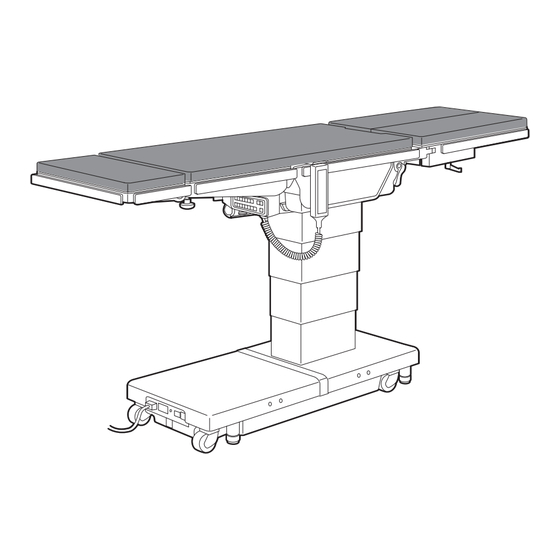
Section Introduction 3.1 Main unit Back section attaching/ Kidney bridge(*3) Table pads detaching lever Leg section(*2) Seat section Back section(*2) Head section(*2) Leg section outstretching handle Leg section fixing lever Head section Leg section flexing lever Fig. B flexing lever Hand controller Side rail Head section... -
Page 18: Hand Controller
3.2 Hand controller Power lamp Pilot lamp Battery lamp Reverse Trendelenburg: Trendelenburg: Head down Head up Lateral tilt: Left down Lateral tilt: Right down Back section down Back section up Table up Table down (Lock operating table) Slide to foot Slide to head Kidney bridge: Up Kidney bridge: Down... -
Page 19: Cordless Hand Controller (Optional)
If the motor gets overheated you will not be able to operate the table. When overheat occurs, about 60 minutes of rest will be needed to operate the table as usual. • Up to 3 channels can be set on the cordless hand controller. If you need the setting, contact your distributor or Mizuho. -
Page 20: Foot Switch (Optional)
3.4 Foot switch (optional) ■ Common to MOT-VS600 Reverse Trendelenburg: Lateral tilt: Table up Head up Right down Table down Trendelenburg: Lateral tilt: Head down Left down... -
Page 21: Operation
Operation 4.1 Installation and battery charging • Use the equipotential wire to ground the equipotential terminal to the medical grounding terminals. CAUTION Prepare the equipotential wire yourself. • When moving this product, carry it out with two or Equipotential more persons. terminal Equipotential wire ■... - Page 22 ■ Installation space This product requires the installation space shown as below. 2.5 m (98.43 in) or more 2.5 m (98.43 in) 2.5 m (98.43 in) or more or more 2.5 m (98.43 in) or more...
- Page 23 2 years. Once it reaches its replacement time, request Power cord your distributor or Mizuho for a battery replacement. When turning on the power switch, battery charging starts. • The life-span for the battery While charging, the battery indicator sequentially lights up orange.
- Page 24 ■ Attaching the hand controller Align the connector with the guide and insert it into the receptacle properly. Insert the connector ■ Detaching the hand controller Turn the connector ring in the direction of the arrow until it stops. Pull out the connector. 1.
- Page 25 ■ Using the self-diagnostic function This product is equipped with an embedded self-diagnostic function capable of checking the communication status between the main unit and the hand controller. Connect the power connector of the product and the medical grade outlet with the power cord. Press on the hand controller.
- Page 26 Light receiving • If operation of the cordless section of the hand controller causes other cordless hand controller electric devices to start, or the operating table is started by another remote control, contact your distributor or Mizuho.
-
Page 27: Turning On/Off The Power
4.2 Turning on/off the power ■ When the medical grade outlet is used ㅡ Turning on the power Turn on the power switch on the base. NOTE The power switch (green) and the battery indicator will be lighted on. • In an emergency or when turning off the power Battery indicator completely, disconnect the... - Page 28 ㅡ Turning off the power When the power is turned on, press on the hand NOTE controller. If you turn off the power switch on the base before The power lamp (green) on the hand controller goes out. pressing on the hand controller, the battery power Power lamp (Green·go out) will be turned on.
- Page 29 ■ When the battery is used ㅡ Turning on the power NOTE When the power cord is not connected to the power When using the battery, the connector or the power switch on the base is turned off, power is turned off press on the hand controller. automatically 15 minutes The power lamp (green) and battery lamp (orange) light up, and the after the last operation.
-
Page 30: Operating The Emergency Stop Switch
4.3 Operating the emergency stop switch In an emergency, you can stop the operating table from moving by pressing the emergency stop switch. The emergency stop switch must be used only in an emergency. WARNING ■ Operating in an emergency Press the emergency stop switch. -
Page 31: Fixing And Unfixing The Operating Table
4.4 Fixing and unfixing the operating table ■ Fixing the operating table After activating the brake, check that the operating table is fixed securely. WARNING Press first and then NOTE The brake is activated to fix the operating table, and the power lamp • The operating table can be fixed or unfixed once on the base turns green. Operations such as raising the tabletop will not operate until the fixing of the operating table is completed. -
Page 32: Tilting The Tabletop Laterally
4.5 Tilting the tabletop laterally When you tilt the tabletop laterally with a patient on the operating table, make sure to use the fixing accessory for the Mizuho operating table. WARNING The patient may fall from the operating table. ■ Tilting to the left NOTE Press first and then •... - Page 33 ■ Tilting to the right Press first and then NOTE • The maximum angle The tabletop tilts to the right in the view from the head side. achieved in the right down position is 35° from the Right down level position. 35° 35°...
-
Page 34: Trendelenburg
4.6 Trendelenburg When you operate the Trendelenburg operation with a patient on the operating table, make sure to use the fixing accessory for the Mizuho operating table. WARNING The patient may fall from the operating table. ■ Reverse Trendelenburg (Head up) Press first and then NOTE The tabletop moves to the head up position. - Page 35 ■ Trendelenburg (Head down) • Do not operate until the tip of the head section contacts the floor. It may get damaged. CAUTION • Do not operate until the head section fixing handle contacts the base. It may get damaged. Head section fixing handle Press first and then NOTE • The maximum angle The tabletop moves to the head down position. achieved in the head down position is 40°...
-
Page 36: Back Section Up/Down
4.7 Back section up/down Keep your hands away from the following gap during the operation of the table. Otherwise you may get injured. WARNING • Gap between the back section and seat section • Gap between the back section gear and rack Back section gear Back section Seat section... -
Page 37: Changing The Tabletop Height
4.8 Changing the tabletop height Do not move down the tabletop with the leg section bent down at 90°. The tip of the leg section may come in contact CAUTION with the floor or the base and get damaged. ■ Moving up the tabletop Press first and then NOTE The tabletop moves up. •... - Page 38 ■ Moving down the tabletop NOTE • The minimum height from Press first and then the floor to the tabletop The tabletop moves down and stops at the height of 620 mm (24.41 upper surface is 580 mm in) from the floor. (22.83 in)(*1) or 520 mm Once it stops, release the switch and press it once again; the tabletop (20.47 in)(*2).
-
Page 39: Sliding The Tabletop
4.9 Sliding the tabletop NOTE ■ Sliding in the foot direction • The slide’s maximum travel from the center position of Press first and then the tabletop is as follows. The tabletop slides in the foot direction. - Foot direction: 415 mm (16.34 in) - Head direction: 250 mm (9.84 in) •... -
Page 40: Flexing Or Reflexing The Tabletop
4.10 Flexing or reflexing the tabletop Keep your hands away from the following gap during the operation of the table. Otherwise you may get injured. WARNING • Gap between the back section and seat section • Gap between the back section gear and rack Back section gear Back section Seat section... - Page 41 ■ Reflexing the tabletop Do not reflex the tabletop with the operating table lowered. The tabletop including the slide cylinder may CAUTION come in contact with the base and get damaged. Press first and then NOTE [MOT-VS600DK/VS600DHK] The back section bends upward and the seat section turns to the When the kidney bridge is Trendelenburg (head down) position.
-
Page 42: Change Height Of The Kidney Bridge (Mot-Vs600Dk/Mot-Vs600Dhk Only)
4.11 Change height of the kidney bridge (MOT-VS600DK/MOT-VS600DHK only) ■ Moving up the kidney bridge Press first and then NOTE The kidney bridge moves up. • The highest position is 150 mm (5.91 in) from the surface of the tabletop. • The lowest position is the Move up 150 mm same level of the surface of... -
Page 43: Return To Level
4.12 Return to level ■ Return the tabletop to the level position Press first and then NOTE The tabletop from the Trendelenburg, lateral tilting, back section up/ Elevation, sliding and braking do not function. down, flexing and *kidney bridge lifting positions will return to the level position. * MOT-VS600DK/MOT-VS600DHK only... -
Page 44: Adjusting The Head Section
4.13 Adjusting the head section The head section can be bent in 15° increments, to 4 different positions upward (maximum 60°) and to 6 different positions downward (maximum 90°). The head section can also be detached. The head section weighs 7 kg (15.4 lbs). Pay special attention when handling it. It may drop and cause damage or injury. WARNING ■ Head section up/down Pull the head section flexing lever toward the head NOTE direction. The head section can be bent upward and When bending upward, the downward. - Page 45 ■ Attaching the head section Make sure to tighten the head section fixing handles securely. If the head section moves with the handles in a WARNING loosened state, the patient may get injured. • Make sure to insert the head section into the back section completely. If the operating table is used with CAUTION the head section inserted incompletely, it may get damaged.
-
Page 46: Attaching/Detaching The Back Section
4.14 Attaching/Detaching the back section The back section can be detached. The back section weighs 10 kg (22 lbs). Pay special attention when handling it. It may drop and cause damage or injury. WARNING ■ Detaching the back section Do not detach the back section while the head section is inserted into it. - Page 47 ■ Attaching the back section NOTE • Make sure that the back section is inserted You can install the optional completely. If the operating table is used without the WARNING dedicated accessories to the back section being completely inserted into it, the back section insertion shafts.
- Page 48 ■ Attaching the back section If the back section insertion shaft’s right and left positions are misaligned, attach the back section according to the following procedures. NOTE Make sure that the back section is inserted completely. If You can install the optional the operating table is used without the back section WARNING dedicated accessories to the...
-
Page 49: Adjusting The Leg Section
4.15 Adjusting the leg section The leg section can be bent, stretched outward and detached separately on the left and right side. The leg section can be bent downwards by up to 90° and stretched outwards by up to 50° (center of the first joint) or 40° (center of the second joint). The leg section weighs 8 kg (17.6 lbs) (each). Pay special attention when handling it. It may drop and cause damage or injury. - Page 50 ■ Outstretching the leg section Make sure to tighten the leg section outstretching handle securely. If the leg section moves with the WARNING handle in a loosened state, the patient may get injured. Hold the tip of the leg section and loosen the leg section NOTE outstretching handle.
- Page 51 ■ Detaching the leg section Attach and detach the leg section with it horizontally positioned. Otherwise it may drop and cause damage WARNING or injury. Hold the leg section firmly and pull the leg section out while pressing the leg section fixing lever. Leg section fixing lever ■ Attaching the leg section After attaching the leg section, check that the leg section is inserted completely by shaking the leg WARNING section back and forth.
-
Page 52: Maintenance And Inspection
Mizuho for repairs. Otherwise it may cause problems during WARNING surgery. Inspect the items below. If there is any problem, request your distributor or Mizuho for repair. (1) Table pads ㅡ Before use • Check all the table pads for any damage. - Page 53 (3) Tabletops ㅡ Before use • Check all the tabletops for any damage. ㅡ After use • Check all the tabletops for any damage or dirt. (4) Hand controller ㅡ Before use • Press the power ON/OFF switch on the hand controller to see if the power lamps on the hand controller and the base light up.
-
Page 54: Cleaning And Disinfection
WARNING • Make sure to unplug the power cord and turn off the main power when cleaning and disinfecting the operating table. The operating table may actuate and cause injury. • Make sure to use Mizuho authorized disinfectants. Failure to do so may cause the operating table to become discolored or deformed. CAUTION • When cleaning the table pads, take care not to get liquids on the fasteners. If liquids get on the waterproof fasteners, wipe them off quickly. If the waterproof fastener gets... -
Page 55: Periodic Replacement Parts
5.4 Periodic replacement parts Mizuho specifies that the following parts need to be periodically replaced for safety use. The replacement time is a rough standard. Earlier replacement may be required depending on the usage condition and/or usage frequency. Request your distributor or Mizuho for replacements. Hand controller Battery Power cord Caster Brake rubber... -
Page 56: Specification
Specification 6.1 Specification table Product description MOT-VS600D MOT-VS600DH MOT-VS600DK MOT-VS600DHK 1000 mm 1060 mm 1000 mm 1060 mm Highest (39.37 in) (41.73 in) (39.37 in) (41.73 in) Elevation range 520 mm 580 mm 520 mm 580 mm Lowest (20.47 in) (22.83 in) (20.47 in) (22.83 in) Head up... - Page 57 Note 6: Rough dimension Note 7: Company standard (in case that appropriate maintenance and inspection is done) Note 8: Based on Mizuho’s own validation data Note 9: MOT-VS600DK/MOT-VS600DHK only Note 10: IEC 60601-1: 2020, Medical electrical equipment - Part1: General requirements for basic safety and essential...
-
Page 58: External View
6.2 External view MOT-VS600D MOT-VS600DH 240 mm 464 mm 634 mm 698 mm (9.45 in) (18.27 in) (24.96 in) (27.48 in) MOT-VS600DK MOT-VS600DHK 240 mm 464 mm 634 mm 698 mm (9.45 in) (18.27 in) (24.96 in) (27.48 in) 2124 mm (83.62 in) 500 mm (19.69 in) 483 mm... -
Page 59: Troubleshooting
Troubleshooting 7.1 When the hand controller cannot be used ■ Use the auxiliary switch to operate the operating table • The auxiliary switch should be used only in an emergency. • Always watch movement of the operating table when you operate the auxiliary switch. CAUTION The auxiliary switch has no operational restrictions and may come in contact with other parts. -
Page 60: When The Brake Cannot Be Released
7.2 When the brake cannot be released Do not operate the emergency brake release knob with a patient on the operating table. The operating table may tip over resulting in injury. WARNING After turning the emergency brake release knob in the UNLOCK direction, make sure to return it in the LOCK direction. -
Page 61: Before Contacting For Repairs
If the situation does not improve even if countermeasures 1. and 2. are implemented. The battery’s fuse is blown. Request repairs from your distributor or Mizuho. If the situation does not improve even if the above countermeasures are implemented, request repairs from your distributor or Mizuho. - Page 62 Connector ■ Warranty MIZUHO Corporation will repair defective parts of this product without charge for one year from the date of delivery/installment except for cases of damage caused by a third party’s repair, act of nature, improper use or intentional damage. All other warranty terms and conditions are subject to regulations of MIZUHO...
-
Page 63: App.-1 Electromagnetic Compatibility
App.-1 Electromagnetic Compatibility Install and operate according to the EMC information provided in this manual. • Do not use any accessories other than those specified by Mizuho. This can result in increased emissions and reduced immunity. WARNING • Do not use it adjacent to or stacked with other equipment. Normal operation may not be possible due to electromagnetic interference. - Page 64 Guidelines and manufacturer declaration – electromagnetic interference immunity The MOT-VS600D/VS600DK/VS600DH/VS600DHK is intended for use in the electromagnetic environment specified below. The customer or user of the MOT-VS600D/VS600DK/VS600DH/VS600DHK must ensure that it is operated in suchlike environments. Interference Electromagnetic IEC 60601 test level Compliance level immunity tests environment –...
- Page 65 Guidelines and manufacturer declaration – electromagnetic interference immunity (continuation) Conducted disturbances 150 kHz to 80 MHz 150 kHz to 80 MHz Portable and mobile RF induced by radiated RF communications equipment IEC 61000-4-6 (radio devices, incl. antennas or ISM frequencies ISM frequencies cables) should be used no closer to any part of the MOT-VS600D/...
-
Page 66: App.-2 Glossary
App.-2 Glossary Base The light-blue portion of the figure below. Flex/Reflex The back section is bent upward or downward, the seat section moves to the head-up or the head-down position, and the entire tabletop moves to the “Center up” or “Center down.” Lateral tilt Tabletop of the operating table moves to the left-down or the right-down position. Tabletop The light-blue portion of the figure below. - Page 67 Revision Record 2017-03 Ver.1 New release 2017-06 Ver.2 Revision 2017-09 Ver.3 Revision 2017-10 Ver.4 Revision 2019-05 Ver.5 Revision 2019-10 Ver.6 Revision 2020-04-01 Ver.7 Revision 2021-07-05 Ver.8 Revision 2023-07-27 Ver.9 Revision 2023-10-02 Ver.10 Revision 2024-07-26 Ver.11 Revision...
- Page 68 Sales Agent 3-30-13 Hongo, Bunkyo-ku Tokyo 113-0033, Japan https://www.mizuho.co.jp...
Need help?
Do you have a question about the MOT-VS600 and is the answer not in the manual?
Questions and answers